- Written By
Balsara Jay
- Last Modified 30-12-2024
Mutual Induction: Meaning, Working, Solving Examples
Mutual Induction: You might have studied induction earlier. Induction means the transfer of energy without any kind of physical contact. Mutual induction is a part of electromagnetic induction, and hence, here, we will transfer electrical energy from one conducting body to another conducting body without any physical contact.
It is a kind of static EMI where induction occurs without any motion. Static EMI further has two types of induction viz. \((1)\) self-induction (which means inducing electricity in itself) and \((2)\) mutual induction (which means inducing electricity in another coil). In this article, we will look into the details about mutual induction, the factors on which it depends and its applications.
Learn About Electromagnetic Induction Here
How does Mutual Induction Work?
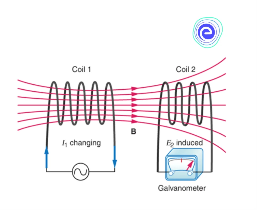
Consider the given diagram to understand clearly about mutual induction. Here, we have two coils: coil \(1\) and coil \(2\). Coil \(1\) is connected to a variable supply, while coil \(2\) is connected to a galvanometer.
When a variable current passes through the coil, a variable magnetic flux is induced in it. Due to this variable magnetic flux inside the coil, it will induce its own emf inside it. But apart from this, the magnetic flux from coil \(1\) is linked with coil \(2\) also. Hence, just like coil \(1\), a variable magnetic flux is also present in coil \(2\). Thus, coil \(2\) will also induce its own emf in the direction which opposes the changing magnetic flux in it. Due to this emf, a current is produced in it, and hence, we have induced electrical energy from one coil to another without making any physical contact.
Hence, the flux linked in coil \(2\) is due to current passing in coil \(1\):
\({\Phi _2} \propto {I_1}\)
\(\therefore \,{M_{21}} = \frac{{{\Phi _2}}}{{{I_1}}}\)
Hence, the mutual inductance of coil \(2\) with respect to coil \(1\) is defined as the flux linked with coil \(2\) per unit current passing through coil \(1\).
\({M_{21}}{I_1} = {\Phi _2}\)
Differentiating this equation with respect to time:
\({M_{21}}\frac{d}{{dt}}{I_1} = \frac{d}{{dt}}{\Phi _2}\)
\(\therefore \,{\varepsilon 2} = – {M{21}}\frac{{d{I_1}}}{{dt}}\)
\(\therefore \,{M_{21}} = \frac{{ – {\varepsilon _2}}}{{\frac{{d{I_1}}}{{dt}}}}\)
Hence, mutual inductance is also defined as the negative of emf induced in coil \(2\) per unit rate of change in current with respect to time in coil \(1\). The negative sign here indicates that the direction of emf produced in coil \(2\) is in a direction opposite to the changing current in coil \(1\).
From this, we can say that mutual inductance mainly depends on the following factors:
- Distance between both the Coils
- Orientation of both the Coils
- Coupling between both the Coils
Reciprocity Theorem
Mutual inductance of coil \(2\) with respect to current passing in coil \(1\) is given by \({M_{21}} = \frac{{{\Phi _2}}}{{{I_1}}}\) whereas mutual inductance of coil \(1\) with respect to coil \(2\) is given by \({M_{12}} = \frac{{{\Phi _2}}}{{{I_1}}}\).
Since \({\Phi _1} = {\Phi _2}\), then and current induced in coil \(2\) is equal to the current supplied in coil \(1\), then
\({M_{12}} = {M_{21}}\)
This theorem is known as the reciprocity theorem.
It states that the mutual induction in coil \(2\) due to coil \(1\) is always equal to the mutual induction of coil \(1\) due to coil \(2\).
Coupling
The coupling of inductors means how exactly are both the coils placed with respect to each other. Let the self-inductance of the individual coils used for mutual inductance be \({L_1}\) and \({L_2}\). Then the net mutual inductance of both the coils will be given by:
\(M = K\sqrt {{L_1}{L_2}} \)
Here, \(K\) is known as the coefficient of coupling of both the coils
Self-inductance of coil \(1\) is \({L_1} = \frac{{{\Phi _1}}}{{{I_1}}}\) and self-inductance of coil \(2\) is \({L_2} = \frac{{{\Phi _2}}}{{{I_2}}}\). Multiplying both the self-inductance:
\({L_1}{L_2} = \frac{{{\Phi _1}}}{{{I_1}}}\frac{{{\Phi _2}}}{{{I_2}}}\)
\(\therefore \,{L_1}{L_2} = {M_{21}}{M_{12}}\)
But, \({{M_{21}} = {M_{12}} = M}\)
\(\therefore \,M = \sqrt {{L_1}{L_2}} \)
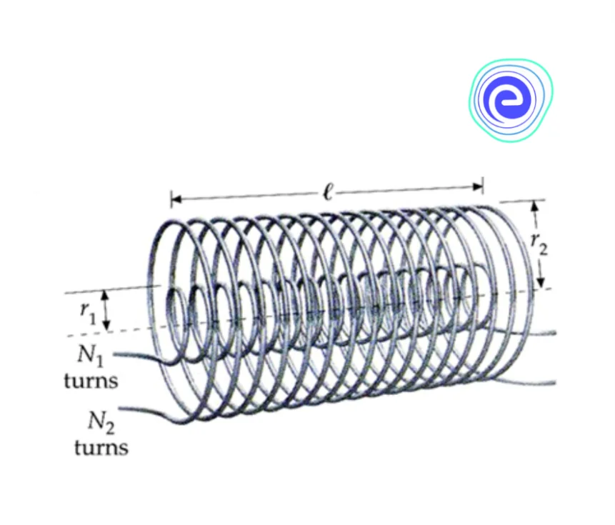
But, this one case is the ideal case. It will only apply if both the coils are looped over one other like the given diagram. Here, both the coils ensure that there is no magnetic flux leakage between both coils. This type of coupling is known as coaxial coupling.
For any other type of coupling other than coaxial coupling, we use:
\(M = K\sqrt {{L_1}{L_2}} \)
If, \(K{\rm{ < 0}}{\rm{.5}}\), then the coils are said to be loosely coupled
If \(K \ge 0.5\), then the coils are said to be tightly coupled
And, \(K{\rm{ = 1}}\), then the coils are said to be coaxially coupled
The best example of the use of mutual induction is a transformer. Transformer basically works on the principle of mutual induction.
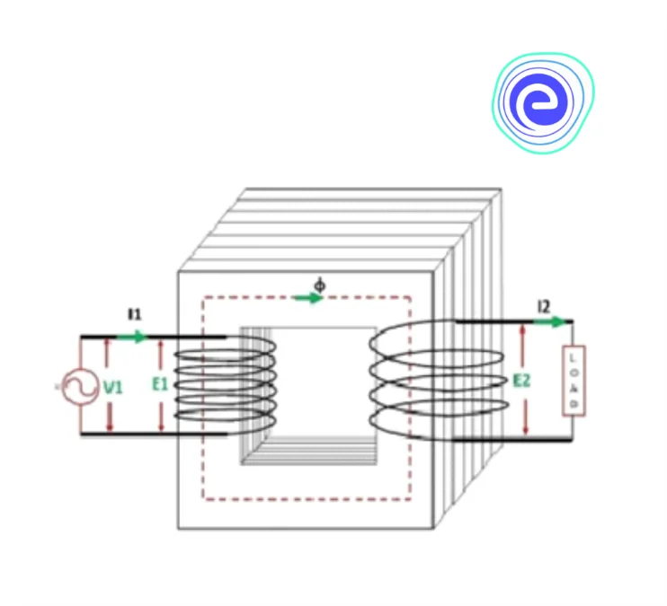
The diagram shows a simple transformer for your understanding. Here, we have two coils on the two limbs of a core. This core is made up of soft iron because it has a high magnetic susceptibility so that the magnetic field lines can easily pass from one coil to the other.
Here, the coil where electricity is supplied is known as the primary coil, and the output side is known as the secondary coil. When an alternating current is supplied to the primary coil, a changing magnetic flux is produced through it. This changing magnetic flux gets linked with the secondary coil, and hence the secondary coil induces a back emf in itself.
Let’s say the number of turns in the primary coil is \({N_1}\) and the number of turns in the secondary coil is \({N_2}\). According to Faraday’s law of electromagnetic induction, the potential difference across the primary and secondary coil will be:
\({V_1} = – {N_1}\frac{{d\Phi }}{{dt}}\) and \({V_2} = – {N_2}\frac{{d\Phi }}{{dt}}\)
So, from both these equations:
\(\frac{{{V_1}}}{{{V_2}}} = \frac{{{N_1}}}{{{N_2}}}\)
Hence, the potential difference across the coil is directly proportional to the number of turns. This means the more the number of turns, the more is the voltage across the coil.
The ratio \(\frac{{{N_2}}}{{{N_1}}}\) is known as the turns ratio.
\(r = \frac{{{N_2}}}{{{N_1}}}\)
If, \(r > 1\), then \({{N_2} > {N_1}}\). Therefore, \({{V_2} > {V_1}}\) which means the voltage in the secondary coil is greater than the voltage in the primary coil. This type of transformer is known as a step-up transformer where the voltage across the primary coil is stepped up in the secondary coil. These types of transformers are generally used in power generating stations where voltage is stepped up to a higher voltage than generated voltage and is transmitted across the transmission lines.
If, \(r < 1\), then \({{N_1} > {N_2}}\). Therefore, \({{V_1} > {V_2}}\) which means the voltage in the primary coil is greater than the voltage in the secondary coil. This type of transformer is known as a step-down transformer where the voltage across the secondary coil is stepped up in the primary coil. These types of transformers are generally used in distribution systems or in secondary power stations where voltage is stepped down to a lower voltage than the incoming voltage from the transmission line and further ready to be distributed among the loads.
Since power on both the sides of a transformer remains the same, we can write:
\({{V_1}{I_1} = {V_2}{I_2}}\)
\(\frac{{{I_1}}}{{{I_2}}} = \frac{{{V_2}}}{{{V_1}}} = r\)
Hence, if the transformer is a step-up transformer, the current in the secondary coil decreases. This helps us avoid a high amount of copper losses during transmission. In contrast, this goes reverse for a step-down transformer.
Solved Examples on Mutual Induction
Q.1. Two long solenoids having length \(L\) and cross-sectional area \(A\) are placed in such a way that their axis coincide. Find the mutual inductance of this system.
Ans: The magnetic field of a long solenoid is given by:
\(B = \frac{{{\mu _0}NI}}{L}\)
Hence, if the current is passed through one of the solenoids, its magnetic flux will get linked to the other one inside it. Therefore, the mutual induction of this system will be:
\(M = \frac{{{B_1}A}}{L}\)
\(\therefore \,M = \frac{{{\mu _0}{N_1}{N_2}A}}{L}\)
Q.2. In an ideal transformer, the input voltage is \(110\,V\) and the turns ratio is \(10\). Determine the value of output voltage in the transformer.
Ans: Here, since the turns ratio in the transformer is greater than one, this transformer must be a step-up transformer. Therefore, the voltage in the secondary coil will be given by:
\({V_2} = r{V_1}\)
Substituting the values:
\({V_2} = 10 \times 110\)
\(\therefore \,{V_2} = 1100\,V\)
Summary
Reading this article, we get to know about mutual induction in detail. We studied that mutual induction is a link between two coils where one coil induces emf in the other coil, and the other coil on inducing emf starts generating its own current. But it is not every time necessary for the magnetic flux to completely get linked with the other coil. It may vary, and the mutual induction differs. All this stuff depends on the coefficient of coupling of both the coils. And finally, we learned how mutual induction helps us to study transformers and generate power.
Mutual induction between two coils: \(M = \frac{{{\Phi _1}}}{{{I_1}}}\)
Reciprocity theorem: \({M_{12}} = {M_{21}}\)
Coupling: \(M = K\sqrt {{L_1}{L_2}} \)
Turns ratio of a transformer: \(r = \frac{{{N_2}}}{{{N_1}}}\)
Frequently Asked Questions (FAQs) on Mutual Induction
Q.1. What is the mutual induction principle?
Ans: Mutual induction works on the principle of electromagnetic induction. When the magnetic field from one coil links to the other coil, the other coil induces its own emf. This process is known as mutual induction.
Q.2. How do you calculate mutual induction?
Ans: Mutual induction of coil \(2\) with respect to coil \(1\) is given by \(M = \frac{{{\Phi _1}}}{{{I_1}}}\).
Q.3. Where is mutual induction used?
Ans: Mutual induction is used in transformers, generators, motors, etc.
Q.4. What is the SI unit of mutual induction?
Ans: The SI unit of mutual induction is Henry \(\left( H \right)\).
Q.5. What is the maximum possible mutual induction?
Ans: Maximum possible mutual induction occurs when the magnetic field through the inducing coil gets completely linked with the induced coil. For example, in coaxial coupling, the ideal value of the coefficient of mutual induction is \(1\).
Know Everything About Electricity Here
We hope this article on Mutual Induction has helped you. If you have any queries, drop a comment below, and we will get back to you.


