B M Sharma Solutions for Chapter: Inductance, Exercise 2: DPP
B M Sharma Physics Solutions for Exercise - B M Sharma Solutions for Chapter: Inductance, Exercise 2: DPP
Attempt the free practice questions on Chapter 4: Inductance, Exercise 2: DPP with hints and solutions to strengthen your understanding. Chapterwise/Topicwise Daily Practice Problems (DPP) Magnetism and Electromagnetic Induction JEE Main & Advanced solutions are prepared by Experienced Embibe Experts.
Questions from B M Sharma Solutions for Chapter: Inductance, Exercise 2: DPP with Hints & Solutions
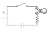
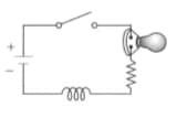
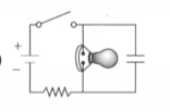
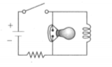
Consider the four circuits shown in the figure, each consisting of a battery, a switch, a light bulb, a resistor and either a capacitor or an inductor. Assume the capacitor has a large capacitance and the inductor has a large inductance but no resistance. The light bulb has high efficiency and glows whenever electric current passes through it.
(i) Describe what the light bulb does in each of circuits (a) through (d) after the switch is closed.
(ii) Describe what the light bulb does in each of circuits (a) through (d) when the switch has been closed for a long time interval and when the switch is opened.
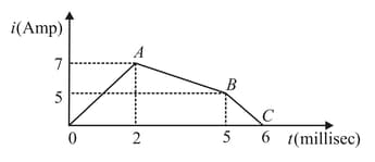
The current through a inductor is shown in the following graph. The induced emf during the time interval to will be:
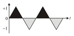
An alternating current of frequency and peak value , as shown in the figure, is applied to the primary of a transformer. If the coefficient of mutual induction between the primary and the secondary is , the voltage induced in the secondary will be
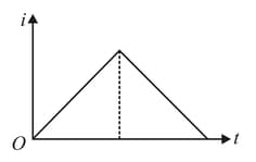
The current in an inductance coil varies with time , according to the graph shown in the figure. Which one of the following plots shows the variation of voltage in the coil with time?
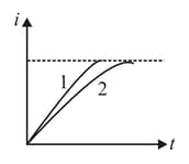
When a certain circuit, consisting of a constant emf , an inductance and a resistance , is closed, the current in it increases with time according to curve . After one parameter is changed, the increase in current follows curve , when the circuit is closed second time. Which parameter was changed and in what direction?
Switch , of the circuit shown in the figure, is closed at
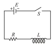
If denotes the induced emf in and , the current flowing through the circuit at time , which of the following graphs is correct?
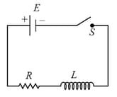
Switch , of the circuit shown in the figure, is closed at . If denotes the induced emf in and , the current flowing through the circuit at time , which of the following graphs is correct?
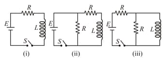
In which of the following circuit is the current maximum just after the switch is closed?