B M Sharma Solutions for Chapter: Electrical Measuring Instruments, Exercise 3: Exercise
B M Sharma Physics Solutions for Exercise - B M Sharma Solutions for Chapter: Electrical Measuring Instruments, Exercise 3: Exercise
Attempt the free practice questions on Chapter 6: Electrical Measuring Instruments, Exercise 3: Exercise with hints and solutions to strengthen your understanding. PHYSICS for Joint Entrance Examination JEE (Advanced) Electrostatics and Current Electricity solutions are prepared by Experienced Embibe Experts.
Questions from B M Sharma Solutions for Chapter: Electrical Measuring Instruments, Exercise 3: Exercise with Hints & Solutions
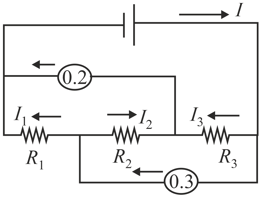
A circuit contains an ideal battery, three resistors and two ideal ammeters. The ammeters read and . After two of the resistors are switched, the readings of the ammeters did not change. Find the battery current.
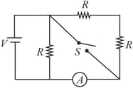
In the circuit shown, battery, ammeter and voltmeter are ideal and the switch is initially closed as shown. When switch is opened,
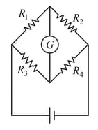
All the resistance in the given Wheatstone bridge have different values and the current through the galvanometer is zero. The current through the galvanometer will still be zero if,
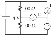
In the figure, the ammeter reads a current of , while the voltmeter reads a potential difference of . The ammeters are identical, and the internal resistance of the battery is negligible (consider all ammeters and voltmeters as non-ideal).
The resistance of the ammeter is, . What is the value of ?
The maximum current in a galvanometer can be . Its resistance is . To convert it into an ammeter of , the resistance should be connected in parallel with galvanometer is . Write the value of .
The current in a conductor and the potential difference across its ends are measured by an ammeter and a voltmeter, respectively. The voltmeter draws negligible currents. The ammeter is accurate, but the voltmeter has a zero error (that is, it does not read zero when no potential difference is applied). Calculate the zero error if the readings for two different conditions are and (in ).
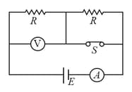
In the circuit shown in the figure the reading of an ideal ammeter is the same with both switches open as with both closed then find the resistance (in ).
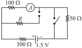
In the circuit shown, and . With the switch open the reading of the ammeter is one-third its reading when is closed. Calculate the resistance of the ammeter (in ).