Embibe Experts Solutions for Chapter: Current Electricity, Exercise 2: Exercise-2
Embibe Experts Physics Solutions for Exercise - Embibe Experts Solutions for Chapter: Current Electricity, Exercise 2: Exercise-2
Attempt the free practice questions on Chapter 24: Current Electricity, Exercise 2: Exercise-2 with hints and solutions to strengthen your understanding. Beta Question Bank for Engineering: Physics solutions are prepared by Experienced Embibe Experts.
Questions from Embibe Experts Solutions for Chapter: Current Electricity, Exercise 2: Exercise-2 with Hints & Solutions
Capacitors and are separately charged from the same battery. They are then allowed to discharge separately through equal resistors-
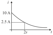
The figure shows, a graph of the current a discharging circuit of a capacitor through a resistor of resistance :
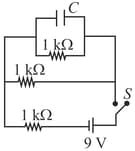
A capacitor is connected to three resistor each of resistance and a battery of emf . The switch has been closed for long time so as to charge the capacitor. When switch is opened, the capacitor discharges with time constant -
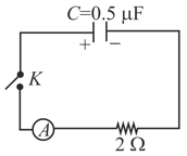
A charged capacitor is allowed to discharge through a resistor by closing the key at the instant . At the instant , the reading of the ammeter falls half the initial value. The resistance of the ammeter is equal to-
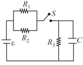
The circuit shown in the figure consist of a battery of emf ; a capacitor of capacitance and three resistor of values and . Initially the capacitor is completely uncharged and the switch is open. The switch is closed at .
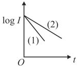
A capacitor of capacity is charged to the steady potential difference and connected in series with an open key and a pure resistor ''. At time , the key is closed. If is the current at time , a plot of log against time '' is as shown in in the graph. Later on of the parameters i.e. or is changed keeping the other two constant, and the graph is recorded. Then-
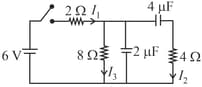
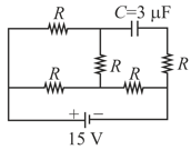
In the circuit shown, the cell is ideal, with emf . Each resistance is of . The potential difference across the capacitor is
In the circuit shown in the figure, the switch is initially open and the capacitor is initially uncharged. and represent the current in the resistance and respectively.