
A wire-frame in the form of a tetrahedron is connected to a . source. The resistances of all the edges of the tetrahedron are equal.
Indicate the edge of the frame that should be eliminated to obtain the maximum,
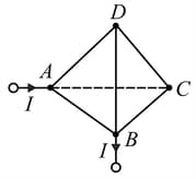
change in the current in the circuit, neglecting the resistance of the leads.
Important Questions on Electricity and Magnetism
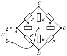
The resistance of each resistor in the circuit diagram shown in is the same and equal to . The voltage across the terminals is . Determine the current in the leads if their resistance can be neglected.
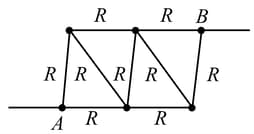
Determine the resistance between points and of the frame formed by nine identical wires of resistance each,
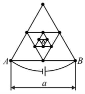
Determine the resistance between points and of the frame made of thin homogeneous wire, assuming that the number of successively embedded equilateral triangles (with sides decreasing by half) tends to infinity. Side is equal to , and the resistance of unit length of the wire is .
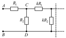
The circuit diagram shown in the figure consists of a very large (infinite) number of elements. The resistances of the resistors in each subsequent element differ by a factor of from the resistances of the resistors in the previous elements. Determine the resistance between points and if the resistances of the first element are and .
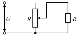
The voltage across a load is controlled by using the circuit diagram shown in the figure. The resistance of the load and of the potentiometer is . The load is connected to the middle of the potentiometer. The input voltage is constant and equal to . Determine the change in the voltage across the load if its resistance is doubled.
Given two different ammeters in which the deflections of the pointers are proportional to current, and the scales are uniform. The first ammeter is connected to a resistor of resistance and the second to a resistor of unknown resistance . At first the ammeters are connected in series between points and (as shown in Fig.).
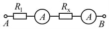
In this case, the readings of the ammeters are and . Then the ammeters are connected in parallel between and
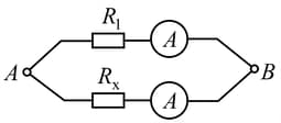
(as shown in Fig,) and indicate and . Determine the unknown resistance of the second resistor.
The key in circuit diagram shown in Fig. can be either in position or
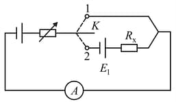
The circuit includes two d.c. sources, two resistors, and an ammeter. The emf of one source is and of the other is unknown. The internal resistance of the sources should be taken as zero. The resistance of the resistors is also unknown. One of the resistors has a varying resistance chosen in such a way that the current through the ammeter is the same for both positions of the key. The current is measured and is found to be equal to .
Determine the resistance denoted by in the diagram.


