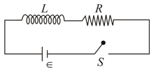
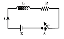
Consider the L-R circuit shown below and choose the correct statement(s).
Important Questions on Electromagnetic Induction
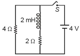
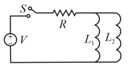
In the figure shown, a circuit contains two identical resistors with resistance and an inductance with An ideal battery of is connected in the circuit. What will be the current through the battery long after the switch is closed?
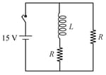
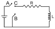
An inductor and a resistor are connected in series to a battery of E.M.F. in a circuit shown below. The key has been kept closed for a long time. Then at , is opened and key is closed simultaneously. At , the current in the circuit will be :
As shown in the figure, a battery of emf is connected to an inductor and resistance in series. The switch is closed at The total charge that flows from the battery, between and ( is the time constant of the circuit) is:
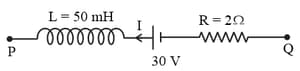
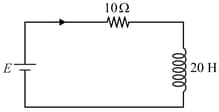
A part of a complete circuit is shown in the figure. At some instant, the value of current I is and it is decreasing at a rate of . The value of the potential difference (in volts) at that instant is-
A inductor coil is connected to a resistance in series as shown in figure. The time at which rate of dissipation of energy (Joule's heat) across resistance is equal to the rate at which magnetic energy is stored in the inductor, is:
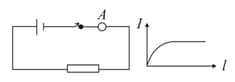
When a voltage is applied at the two ends of a circuit kept in a closed box, it is observed that the current gradually increases from zero to a certain value and then remains constant. What do you think that the circuit contains?
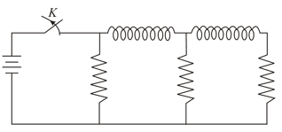
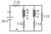
Figure shows a circuit contains three identical resistors with resistance each, two identical inductors with inductance each, and an ideal battery with emf . The current through the battery just after the switch closed is:
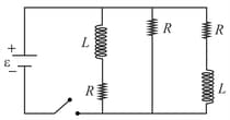
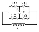
The figure shows a circuit that contains four identical resistors with resistance two identical inductors with inductance and an ideal battery with E.M.F. The current just after the switch is closed will be:
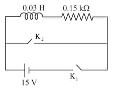
The current at time and respectively for the given circuit is :
For the given circuit the current through the battery when the key in closed and the steady state has been reached is
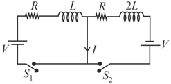
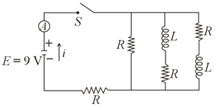
In the circuit shown below, all the inductors (assumed ideal) and resistors are identical. The current through the resistance on the right is after the key has been switched on for along time. The currents through the three resistors (in order, from left to right) immediately after the key is switched off are-