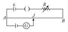
Correct diagram for the determination of internal resistance of a primary cell by potentiometer is
Important Questions on Current Electricity
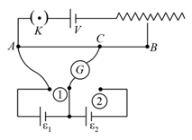
In the given potentiometer circuit arrangement, the balancing length is measured to be . When the galvanometer connection is shifted from point (1) to point (2) in the given diagram, the balancing length becomes . The ratio of the emf of two cells is:
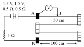
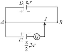
A potentiometer wire of length is connected to a standard cell . Another cell of emf is connected with a resistance and switch (as shown in figure). With switch open, the null position is obtained at a distance of from . The potential gradient in the potentiometer wire is :
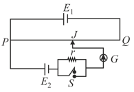
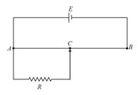
Figure shows a potentiometer. Length of the potentiometer wire is and its resistance is . EMF of the battery is . A resistance of draws current from the potentiometer. What is the voltage across when the sliding contact is at the mid-point of
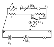
In the given figure, there is a circuit of potentiometer of length . The resistance per unit length is per . Across , a battery of emf and internal resistance is connected. The maximum value of emf measured by this potentiometer is:

infinity
The 'balancing lengths, on the potentiometer wire are found to be and respectively. The value of internal resistance of the cell is: