HARD
Earn 100

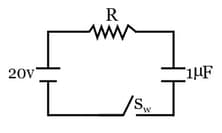
Diagram shows an uncharged capacitor connected in series with a resistor R and an ideal battery. At t=0, switch Sw is closed and it is observed that, when charge on capacitor is 75% of the maximum value then, current in the circuit is 1 A. The value of R is:
Question Image

50% studentsanswered this correctly

Important Questions on Current Electricity

EASY

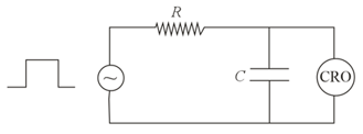
An RC circuit as shown in the figure is driven by a AC source generating a square wave. The output wave pattern monitored by CRO would look close to :

Question Image

MEDIUM
Determine the charge on the capacitor in the following circuit:
Question Image
MEDIUM

For the given input voltage waveform Vin (t), the output voltage waveform V0(t), across the capacitor is correctly depicted by :
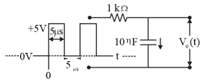
Question Image   

HARD

Question Image

A capacitor of capacitance C=1 μF is suddenly connected to a battery of 100 V through a resistance R=100 Ω. The time taken for the capacitor to be charged to get 50 V is:

(Take ln2=0.69)

MEDIUM
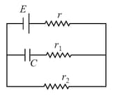
In the given circuit diagram, when the current reaches a steady-state in the circuit, the charge on the capacitor of capacitance C will be:
Question Image
HARD
A parallel plate capacitor (of capacitance C) with circular plates of radius r0 located at position ±α, is connected in series with a resistor R and is charged by a battery of voltage V. Consider a circular loop L of radius r0¯ parallel to the capacitor plates is located at 2¯ the center. Which of the following statements is correct ?
HARD
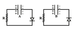
Two identical capacitors A and B, charged to the same potential 5V are connected in two different circuits as shown below at time t=0. If the charge on capacitors A and B at time t=CR is QA and QB respectively, then (Here e is the base of natural logarithm)

Question Image
MEDIUM

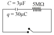
The circuit shown in the figure consists of a charged capacitor of capacity 3 μF and a charge of 30 μC. At time t=0, when the key is closed, the value of current flowing through the 5 MΩ resistor is x μA. The value of x to the nearest integer is

Question Image

MEDIUM

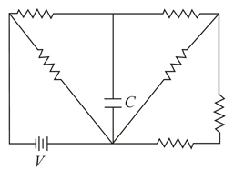
Consider the circuit shown in the figure below:
Question Image

All the resistors are identical. The charge stored in the capacitor, once it is fully charged, is

MEDIUM

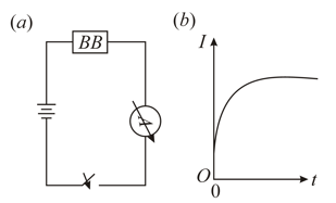
A blackbox (BB) which may contain a combination of electrical circuit elements (resistor, capacitor or inductor) is connected with other external circuit elements as shown below in the figure (a) . After the switch (S) is closed at time t=0 , the current I as a function of time t is shown in the figure b .

Question Image

From this we can infer that the black-box contains
EASY
Tbe dimension of 1/RC, where R is the resistance and C is the capacitance, is the same as that of
MEDIUM
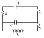
In an LCR circuit as shown below both switches are open initially. Now switch S 1 is closed, S 2 kept open. ( q is charge on the capacitor and τ = RC  is capacitive time constant). Which of the following statement is correct?
Question Image
EASY
L,C and R represent the quantities inductance, capacitance and resistance respectively. The combination which has the dimensions of frequency is
EASY

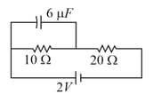
What is the charge on the capacitor in the circuit shown below?
Question Image

HARD
A capacitor is discharging through a resistor R. Consider in time t1, the energy stored in the capacitor reduces to half of its initial value and in time t2, the charge stored reduces to one eighth of its initial value. The ratio t1t2 will be
HARD

In the circuit shown below, the key is pressed at time t=0. Which of the following statement(s) is(are) true?
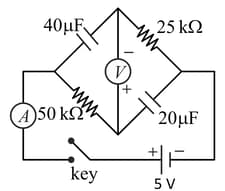
Question Image

MEDIUM
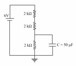
A capacitor of 50μF is connected in a circuit as shown in figure. The charge on the upper plate of the capacitor is _________ μC.
Question Image
MEDIUM

The circuit shown has been connected for a long time. The voltage across the capacitor is, 
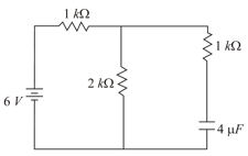
Question Image

MEDIUM
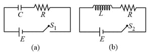
In the given circuits a and b, switches S1 and S2 are closed at t=0 and kept close for a long time. The variation of currents in the two circuits for t0 are shown in the options. (Figures are schematic and not drawn to scale.)
Question Image
HARD
An infinite line charge of uniform electric charge density λ lies along the axis of an electrically conducting infinite cylindrical shell of radius R. At time t = 0, the space inside the cylinder is filled with a material of permittivity ε and electrical conductivity σ . The electrical conduction in the material follows Ohm's law. Which one of the following graphs best describes the subsequent variation of the magnitude of current density j(t) at any point in the material?