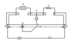
Draw a circuit diagram which can be used to determine the resistance of a given wire. Explain the principle of the experiment and give the formula used.

Important Questions on Current Electricity
In which bar is drift speed of free electrons greater ?
Two material bars and of equal area of cross-section, are connected in series to a supply. A is made of usual resistance wire and of an -type semiconductor.
If the same constant current continues to flow for a long time, how will the voltage drop across and be affected ?
Justify each answer.
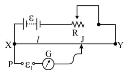
The diagram below shows a potentiometer set up. On touching the jockey near to the end $X$ of the potentiometer wire, the galvanometer pointer.

deflects to left. On touching the jockey near to end $Y$ of the potentiometer, the galvanometer pointer again deflects to left but now by a larger amount. Identify the fault in the circuit and explain, using appropriate equations or otherwise, how it leads to such a one-sided deflection.
Following circuit was set up in a metre bridge experiment to determine the value of of an unknown resistance.

Write the formula to be used for finding from the observations.
