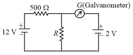
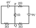
For which value of resistance galvanometer shows zero deflection for following below electrical circuit.
Important Questions on Electricity
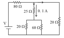
In the circuit shown, the current in the resistor is:
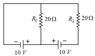
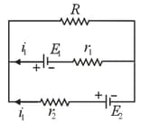
Two batteries with e.m.f. and are connected in parallel across a load resistor of . The internal resistance of the two batteries are and respectively. The voltage across the load lies between,
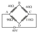
Four resistance and and make the arms of a quadrilateral . Across is a battery of emf and internal resistance negligible. The potential difference across in is __________
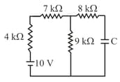
When a capacitor is fully charged as shown in the following figure, then current drawn from the cell is
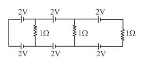
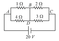
In the above circuit the current in each resistance is:
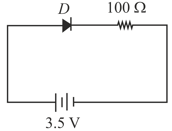
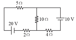
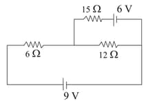
In the figure shown, the current in the battery is close to :
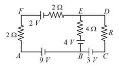
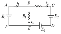
For the circuit given below, the Kirchhoff's loop rule for the loop is given by the equation
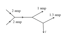
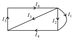
The figure below shows currents in a part of electric circuit. The current is
In the given circuit, the electric currents through and respectively are
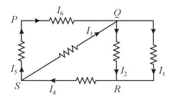
In the following network, and The values of and respectively are
A current of flows through a resistor represented by the circuit diagram. The current in the resistor is: