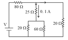
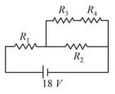
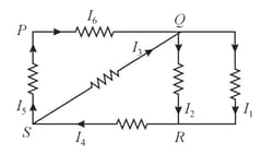
In the circuit shown in diagram, the current through,
Important Questions on Current Electricity
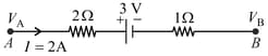
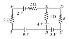
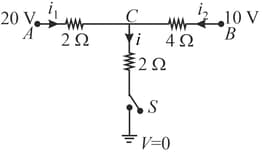
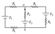
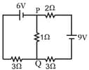
The potential difference between the points and in the given figure is
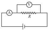
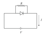
A current of flows through a resistor represented by the circuit diagram. The current in the resistor is:
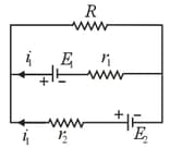
Two batteries with e.m.f. and are connected in parallel across a load resistor of . The internal resistance of the two batteries are and respectively. The voltage across the load lies between,
The figure below shows a circuit and its input voltage as a function of time .
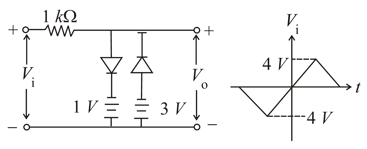
Assuming the diodes to be ideal, which of the following graphs depicts the output voltage as function of time
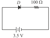
For a diode connected in parallel with a resistor, which is the most likely current -voltage characteristic graph?
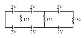
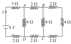
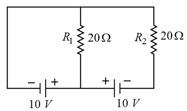
In the above circuit the current in each resistance is:
In the circuit shown, the current in the resistor is:
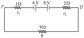
Two batteries of emfs and with internal resistances and are connected in a circuit with a resistance of as shown in figure. The current and potential difference between the points and are,