
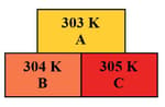
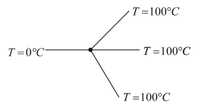
In the given diagram, the possible direction of heat energy transformation is
Important Questions on Thermal Properties of Matter
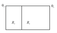
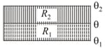
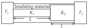
Consider a pair of insulating blocks with thermal resistances , and as shown in the figure. The temperature at the boundary between the two blocks is
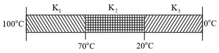
Three rods of identical cross-section and length are made of three different materials of thermal conductivity and , respectively. They are joined together at their ends to make a long rod (see figure). One end of the long rod is maintained at and the other at (see figure). If the joints of the rod are at and in steady and there is no loss of energy from the surface of the rod, the correct relationship between and is :
Consider a ball of mass attached to one end of a spring and immersed in water. Assume the complete system is in thermal equilibrium. The spring is now stretched to and the mass is released so that it vibrates up and down. Estimate the change in temperature of water before the vibrations stop.
(Specific heat of the material of the ball and Specific heat of water )
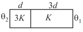
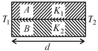
The temperature at the junction of two insulating sheets, having thermal resistances and as well as top and bottom temperatures and (as shown in figure) is given by :
A metallic prong consists of rods made of the same material, cross-section, and same lengths as shown.
The three forked ends are kept at and the handle end is at The temperature of the junction is
Two rods A and B of different materials are welded together as shown in figure. Their thermal conductivities are and . The thermal conductivity of the composite rod will be
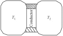
A thin piece of thermal conductor of constant thermal conductivity insulated on the lateral sides connects two reservoirs which are maintained at temperatures, and, as shown. Assuming that the system is in steady-state, which of the following plots best represents the dependence of the rate of change of entropy on the ratio of temperatures,
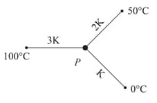
Three rods of same dimensions have thermal conductivities and . They are arranged as shown in the figure below. Then in the steady state the temperature of the junction is
| Heat flow | Electrostatics |


