
EASY
Earn 100
Select the correct phasor diagram of the circuit having only resistance.
50% studentsanswered this correctly
Important Questions on Alternating Current
EASY
What is meant by Wattless current? Clarify.
MEDIUM
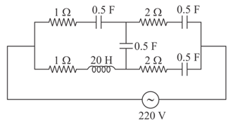
At very high frequencies, the effective impedance of the given circuit will be _________
HARD
Derive an expression for average or mean value of alternating current for half cycle.
MEDIUM
Using , discuss any two special cases for power consumed in an AC circuit.
EASY
When the rms voltages and are measured respectively across the inductor the capacitor and the resistor in a series circuit connected to an source, it is found that the ratio If the rms voltage of the source is then is close to :
EASY
The phaser diagram of the alternating voltage across an unknown device and current flowing through it are shown below.
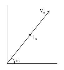
Draw the graphical variation of current and voltage with through this device.
HARD
Assuming expression for impedance in a parallel resonant circuit, state the conditions for parallel resonance. Define resonant frequency and obtain an expression for it.
EASY
A parallel combination of pure inductor and capacitor is connected across a source of alternating EMF . The currents flowing through an inductor and capacitor are and respectively. In this parallel resonant circuit, the condition for currents and is (net RMS current in the circuit)
MEDIUM
An alternating voltage volt is applied to a purely resistive load of . The time taken for the current to rise from half of the peak value to the peak value is:
EASY
An circuit has and connected in series. The quality factor of the circuit is :
HARD
Show that the voltage and current are always in phase when a resistance is connected across an A.C. source. Draw the phasor diagram for it. To tune a radio over a frequency range of , inductance ‘L’ is kept constant and the corresponding capacitance is varied from . Compare .
EASY
An alternating emf source of at is connected to a circuit of resistance and inductance of . What is the phase difference between current and emf
EASY
A small signal voltage is applied across an ideal capacitor :
EASY
The phase difference between current and voltage in an ac circuit containing resistance only is
HARD
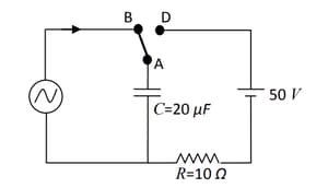
At time , terminal in the circuit shown in the figure is connected to by a key and an alternating current , with and starts flowing in it with the initial direction shown in the figure. At , the key is switched from B to D. Now onwards only A and D are connected. A total charge flows from the battery to charge the capacitor fully. If and the battery is ideal with of , identify the correct statement(s).
EASY
An alternating voltage is connected to a capacitor through an AC ammeter. The reading of the ammeter is
EASY
A sinusoidal voltage with a frequency of is applied to a series circuit with a resistance of , inductance of and a capacitance of . The magnitude of impedance of the circuit is close to
MEDIUM
A bulb is connected to an source of . Then the current flowing through the bulb is
EASY
Out of the following graphs, which graph shows the correct relation (graphical representation) for LC Parallel resonant circuit?
HARD
If the input voltage to the circuit below is given by the output voltage is given by .
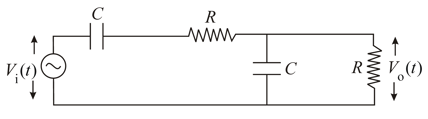
Which one of the following four graphs best depict the variation of vs ?


