
MEDIUM
Earn 100
The graph between inductive reactance and frequency is
50% studentsanswered this correctly
Important Questions on Alternating Current
EASY
EASY
EASY
MEDIUM
EASY
EASY
EASY
MEDIUM
HARD
EASY
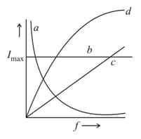
Three identical emf sources are attached to a single circuit element: a resistor, a capacitor, or an inductor. The current amplitude is then measured as a function of frequency. Which one of the following curve corresponds to inductive circuit?
EASY
The phase difference between voltage and current when an ac source is connected to an inductor. :
HARD
EASY
Statement-I: The reactance of an AC circuit is zero. It is possible that the circuit contains a capacitor and an inductor.
Statement-II: In AC circuit, the average power delivered by the source never becomes zero.
In the light of the above statements, choose the correct answer from the options given below
HARD
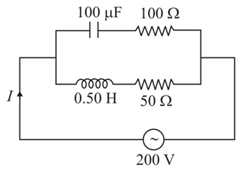
In the given circuit the source has . Considering the inductor and capacitor to be ideal, what will be the current flowing through the circuit?
MEDIUM
EASY
EASY
EASY
EASY
MEDIUM


