
EASY
JEE Main/Advance
IMPORTANT
Earn 100
The instantaneous voltages at three terminals marked and are given by and . An ideal voltmeter is configured to read rms value of the potential difference between its terminals. It is connected between points and and then between and . The reading(s) of the voltmeter will be
50% studentsanswered this correctly
Important Questions on Alternating Current
EASY
JEE Main/Advance
IMPORTANT
EASY
JEE Main/Advance
IMPORTANT
MEDIUM
JEE Main/Advance
IMPORTANT
MEDIUM
JEE Main/Advance
IMPORTANT
MEDIUM
JEE Main/Advance
IMPORTANT
MEDIUM
JEE Main/Advance
IMPORTANT
EASY
JEE Main/Advance
IMPORTANT
Hysteresis loops for two magnetic materials and are given below :
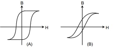
These materials are used to make magnets for electric generators, transformer core and electromagnet core. Then it is proper to use :
MEDIUM
JEE Main/Advance
IMPORTANT
An circuit is equivalent to a damped pendulum. In an circuit the capacitor is charged to and then connected to the and as shown below:
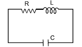
If a student plots graphs of the square of maximum charge on the capacitor with time for two different values of then which of the following represents this graph correctly? (Plots are schematic and not drawn to scale)


