HARD
Earn 100
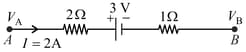
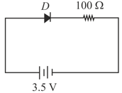
The potential difference for the circuit shown in figure is . Find the value of .
50% studentsanswered this correctly
Important Questions on Current Electricity
MEDIUM
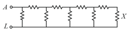
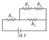
All the resistors are identical. The ratio is
EASY
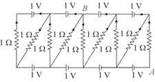
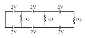
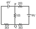
The potential difference between the points and in the given figure is
MEDIUM
EASY
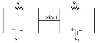
In the circuit, wire is of negligible resistance. Then
HARD
MEDIUM
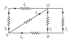
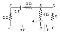
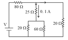
If a current of magnitude, flows through the resistor marked , what is the potential difference measured between points and ?
EASY
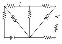
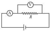
In the above circuit the current in each resistance is:
HARD
EASY
MEDIUM
MEDIUM
MEDIUM
HARD
The figure below shows a circuit and its input voltage as a function of time .
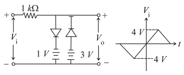
Assuming the diodes to be ideal, which of the following graphs depicts the output voltage as function of time
MEDIUM
A current of flows through a resistor represented by the circuit diagram. The current in the resistor is:
EASY
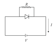
For a diode connected in parallel with a resistor, which is the most likely current -voltage characteristic graph?
MEDIUM
MEDIUM
Two batteries with e.m.f. and are connected in parallel across a load resistor of . The internal resistance of the two batteries are and respectively. The voltage across the load lies between,
HARD
MEDIUM
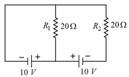
In the circuit shown, the current in the resistor is:
EASY