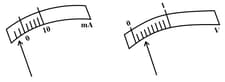
The rest positions of the needles in a milliammeter and voltmeter when not being used in a circuit are shown in the figure. The 'zero error' and 'least count' of these two instruments are
Important Questions on Electricity
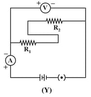
The only correct statement for the two circuits X and Y shown below:
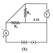
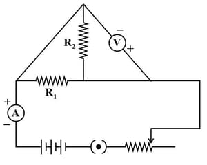
The only correct statement for the following circuit is:
Three students (A), (B) and (C) connect their two given resistor and in the manner shown below:
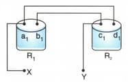
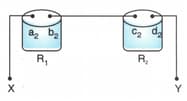
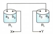
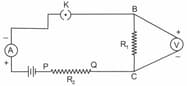
They connect the terminals marked X and Y above to the two terminals marked X and Y in the circuit given below:
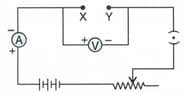
They record the ammeter readings for different positions of the rheostat and the corresponding voltmeter readings . The average value of the ratio in their observations would be minimum for:
To study the dependence of current on the potential difference across a resistor, two students used the two set-ups shown in figure (A) and (B) respectively. They kept the contact in different positions marked , , , , in the two figures.
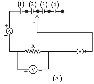
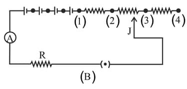
For the two students, their ammeter and voltmeter readings will be minimum when the contact is in the position:
While performing the experiment to study the dependence of current on potential difference across a resistor, the following observations were made by four students, A, B, C and D.
| Student | Reading | Reading | Reading |
| A | |||
| B | |||
| C | |||
| D | |||
The student who made the wrong observation is:
A battery (of internal resistance ) is connected across a resistor and a switch in series, as shown:
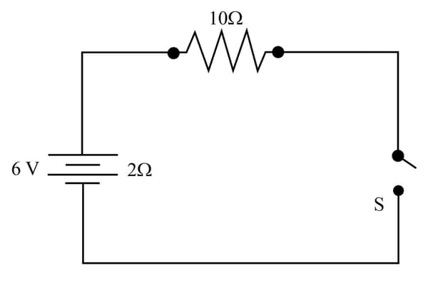
If the switch is kept in the off position, as shown in the figure, then:
A student set up his circuit for finding the equivalent resistance of a series combination of two given resistors and in the manner as shown below. He did not obtain the correct result in his experiment because of a mistake in the circuit. This mistake can be corrected by shifting the component: