
This diagram shows an arrangement to deflect protons from a source to a detector using a magnetic field. The charge on each proton is A uniform magnetic field exists only within the area shown. Protons move from the source to the detector in the plane of the paper.
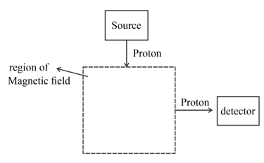
(c) Two changes to the magnetic field in the area shown are made. These changes allow an electron with the same speed as the proton to be deflected along the same path as the proton. State the two changes made.
Important Questions on Motion of Charged Particles
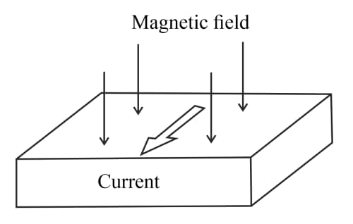
This diagram shows a thin slice of semiconductor material carrying a current in a magnetic field at right angles to the current.

(a) The current in the slice is due to the movement of free electrons.
(i) Add and signs to the diagram to show the charge separation caused by the Hall effect. Explain why the charges separate.
This diagram shows a thin slice of semiconductor material carrying a current in a magnetic field at right angles to the current.
(a) The current in the slice is due to the movement of free electrons.
(ii) Explain how an electron can eventually move in a straight line along the slice.
This diagram shows a thin slice of semiconductor material carrying a current in a magnetic field at right angles to the current.

(b) The Hall voltage is measured using the same slice of semiconductor, the same current and the same magnetic field, but with the laboratory at two temperatures, one significantly higher than the other. Describe and explain the changes in the magnitude of the number density, the drift velocity of the charge carriers and the Hall voltage in the two experiments.
This diagram shows an electron tube. Electrons emitted from the cathode accelerate towards the anode and then pass into a uniform electric field created by two oppositely charged horizontal metal plates.
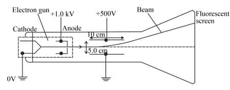
(a) (i) Explain why the beam curves upwards between the plates.
This diagram shows an electron tube. Electrons emitted from the cathode accelerate towards the anode and then Explain why the beam curves upwards between the plates pass into a uniform electric field created by two oppositely charged horizontal metal plates.
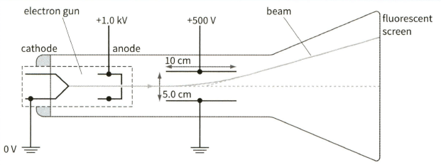
Explain how the pattern formed on the fluorescent screen shows that all the electrons have the same speed as they leave the anode.
This diagram shows an electron tube. Electrons emitted from the cathode accelerate towards the anode and then Explain why the beam curves upwards between the plates pass into a uniform electric field created by two oppositely charged horizontal metal plates.

(b) Write down an equation relating the speed of the electrons v to the potential difference between the anode and the cathode.
This diagram shows an electron tube. Electrons emitted from the cathode accelerate towards the anode and then explain why the beam curves upwards between the plates pass into a uniform electric field created by two oppositely charged horizontal metal plates.

(c) The deflection of the beam upwards can be cancelled by applying a suitable uniform magnetic field in the space between the parallel plates.
(i) State the direction of the magnetic field for this to happen.
This diagram shows an electron tube. Electrons emitted from the cathode accelerate towards the anode and then Explain why the beam curves upwards between the plates pass into a uniform electric field created by two oppositely charged horizontal metal plates.

(c) The deflection of the beam upwards can be cancelled by applying a suitable uniform magnetic field in the space between the parallel plates.
(ii) Write down an equation relating the speed of the electrons , the electric field strength that exists between the plates and the magnetic flux density needed to make the electrons pass undeflected between the plates.


