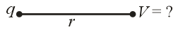
Two charges and are placed at a separation of . Where should a third charge be placed(from first charge), such that it experiences no net force due to these charges?
Important Points to Remember in Chapter -1 - Electric Field and Potential from H C Verma CONCEPTS OF PHYSICS [VOLUME 2] Solutions
1. Electric Charge:
The fundamental property of any substance which produces electric and magnetic fields.
(i) Charge cannot exist without mass, but mass can exist without charge.
(ii) Charge is independent of its velocity.
(iii) Charge at rest produces electrostatic field.
(iv) Charge in motion produces both electric and magnetic fields.
(v) Accelerating charge produces electromagnetic waves.
(vi) Charge of a body is always equal to the integral multiple of charge of an electron, i.e., .
(vii) Total charge of a system is always equal to the algebraic sum of the individual particles of the system.
(viii) Repulsion is a sure test for electrification.
(ix) When a neutral body loses electrons, it gains a positive charge and its mass decreases.
(x) When a neutral body gains electrons, it becomes negatively charged and its mass increases.
(xi) When a charged body is brought close to the neutral body, then charges induce (polarize) in the neutral body.
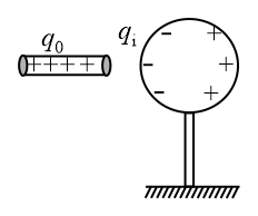
(xii) If two charged bodies are connected by a conducting wire, then charge transfer takes place until their potentials become the same.
(xiii) If two metal spheres of radii and having charge and are connected by a metal wire, then final charges on the spheres are,
and
(xiv) Charge on a conductor:
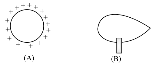
The charge given to a conductor always resides on its outer surface. This is why a solid and hollow conducting sphere of the same outer radius will hold a maximum equal charge. If the surface is uniform, then the charge distributes uniformly on the surface and for irregular surfaces, the distribution of charge and charge density is not uniform. It is maximum where the radius of curvature is minimum and vice versa, i.e., . This is why the charge leaks from sharp points.
2. Charge Distribution:
It may be of two types:
(i) Discrete distribution of charge:
A system consisting of ultimate individual charges.
(ii) Continuous distribution of charge:
An amount of charge distributes uniformly or non-uniformly on a body. It is of the following three types:
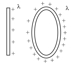
(a) Line charge distribution:
Charge on a line, e.g., charged straight wire, circular charged ring, etc.
Linear charge density, .
S.I. unit is .
Dimension: .
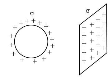
(b) Surface charge distribution:
Charge distributed on a surface, e.g., a plane sheet of charge, conducting sphere, conducting cylinder.
Surface charge density,
S.I. unit is .
Dimension: .
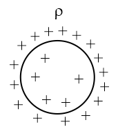
(c) Volume charge density: Charge distributes throughout the volume of the body, e.g., charge on a dielectric sphere, etc.
Volume charge density,
S.I. unit is
Dimension:
3. Coulomb's Law:
The electrostatic force between two point charges is directly proportional to the product of charges and inversely proportional to the square of the distance between them.
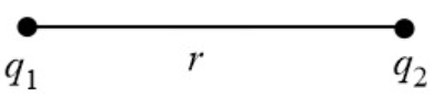
(i) Consider two points charges and are separated by a distance in a vacuum, then the electrostatic force between them is
, where .
(ii) If the charges and are separated by a distance in a medium of dielectric constant , then force between them is
(iii)
(iv) Permittivity : The ability of the medium to allow electric field lines to pass through it is called permittivity.
(v) Relative permittivity (or) dielectric constant :
(a) The ratio of the permittivity of a medium to the permittivity of vacuum.
(b)
(c) It has no units and dimensions.
(d) for vacuum and approximately equal to for air.
(e) always.
(f) increases with an increase in the conductivity of the medium.
(g) for a perfect conductor.
(vi) Coulomb’s law in vector form:
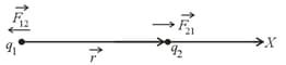
(a) Force on by is,
(b) Charges in a plane (or) space:
Force on by is
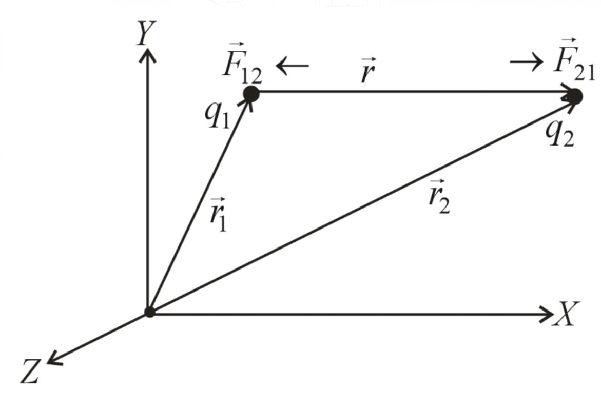
(c) (action–reaction pair)
(vii) Coulomb’s law is applicable to the static point charges.
(viii) The electrostatic force between two charges is independent of the pressure (or) absence of any other charges.
(ix) Electrostatic force is conservative.
(x) The distance between two charges in vacuum is , when the force between the same charges in a medium of dielectric constant to experience the same force is .
(xi) density of ball, density of the liquid.
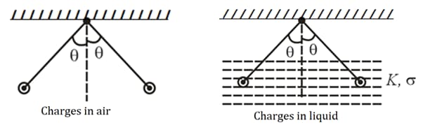
To remain same in both cases, the dielectric constant of the liquid is .
(xii) Two particles each of charge and with masses and are suspended from a common point with the help of identical strings as shown, then
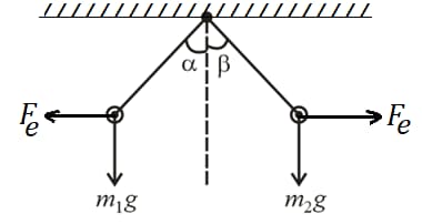
(a) , if
(b) , if
(c) , if
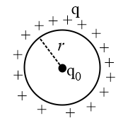
(xiii) A thin wire ring of radius has a charge . When a point charge is placed at its centre, then the tension developed in the ring is
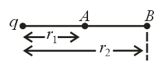
(xiv) If two like charges and are separated by a distance , then one null point exists in between them.
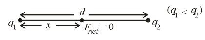
The distance of a null point from the charge of smaller magnitude is .
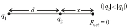
(xv) If two unlike charges are separated, then one null point exists outside the charges and near to the smaller charge. Let be the distance from the charge of smaller magnitude, then
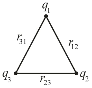
(xvi) Three identical particles each of charge are placed at the corners of an equilateral triangle of side . Then,
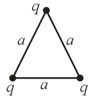
Force on any one charge is .
(xvii) Four identical particles each of charge are placed at the corners of a square of side . Then,
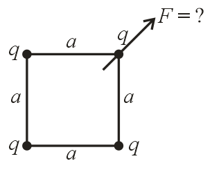
Force on any one charge is .
(xviii) Two identical particles each of charge are moving in a circle of radius under their mutual force of attraction. Then,
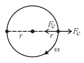
Angular velocity of each particle is or .
4. Electric Field:
The space around a charged particle in which other particles can be influenced.
5. Electric Field Intensity :
The force experienced by a unit positive charge at a point in the electric field.
(i)
(ii) It is a vector.
(iii) S.I. unit: and dimension: .
(iv) The direction of is away from positive charge and towards negative charge.
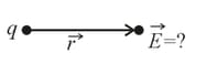
(v) Electric field due to a point charge:
(vi) The force experienced by a charge in an electric field of intensity is .
If the charge is positive, then the force is directed in the direction of the field while if the charge is negative force acts on it in the opposite direction of the field.

6. Electric Field Due to a Uniformly Charged Ring:
(i) Electric field on the axis of a ring:
Consider a circular ring of radius with a charge distributed uniformly over its length. Then, the electric field intensity at a distance from the centre on its axis is
(ii) Electric field at the centre of the ring is .
(iii) Electric field is maximum at .
(iv) The maximum value of the electric field is .
7. Electric Field Due to a Finite Line Charge of Linear Density :
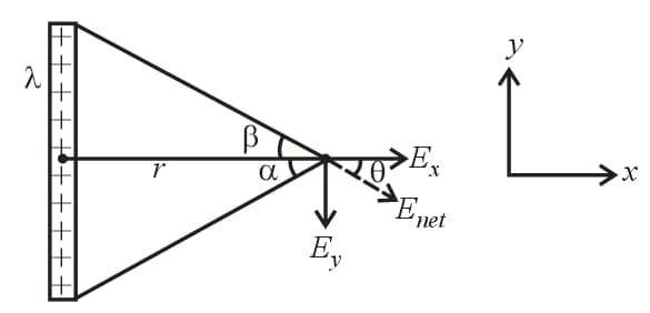
(i) , where is linear charge density and is the perpendicular distance.
(ii)
(iii) and
(iv) Field due to infinite line charge:
(a)
(b)
(c)
(d)
(v) Field due to semi-infinite line charge:
(a)
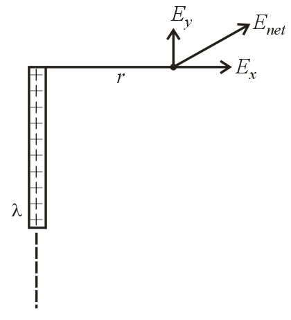
(b)
(c)
(d) and
8. Electric Field Due to a Uniformly Charged Disc:
surface charge density,
radius of the disc.
(i) Electric field on the own axis of the disc is , where is the distance from the centre on the axis.
(ii) For we get
(iii) Electric field due to an infinite disc is independent of distance from it.
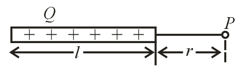
9. Electric Field Due to a Finite Charged Wire on Its Axis:
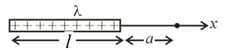
linear charge density, length of the wire and distance of a point at distance from one end of the wire.
(i) Electric field: .
(ii) If , then .
(iii) The rod behaves as a point charge for .
10. Electric Field Due to a Charged Arc:
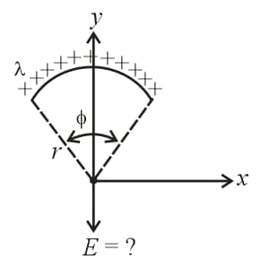
linear charge density, radius of the ring and the angle subtended by the arc at its centre.
(i) , where is in .
(ii) For semi-circular ring, . So, the electric field is .
(iii) For a quarter circle, and .
11. Electric field at the centre of a charged hemispherical shell is , where is surface charge density.
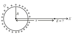
12. Electric Field Due to a Spherical Shell (or) Metal Sphere:
Consider a thin spherical shell of radius with a charge distributed over its surface uniformly.
(i) Field inside the shell, .
(ii) Field on the surface of the shell, .
(or) , where is the charge on the shell, is the radius of shell and is surface charge density.
(iii) Field at a radial distance , outside the shell is
(or)
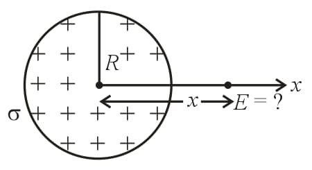
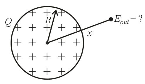
13. Electric Field Due to a Uniformly Charged Non-conducting Sphere:
(i) Field on the surface, (or) , where charge of the sphere, radius of the sphere and volume charge density.
(ii) Field at a radial distance , outside the sphere is
(or)
(iii) Field at a distance from the centre and inside the sphere is,
(or)
(iv) Field at the centre, .
14. Electric Field Due to a Long Uniformly Charged Cylindrical Shell (or) Conducting Cylinder:
(i) Electric field inside the shell, (for ).
(ii) Field outside the shell, , where surface charge density and radial distance.
(iii) Field on the surface, .
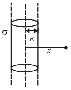
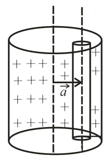
15. Electric Field Due to a Long Uniformly Charged Non-conducting cylinder:
Consider a non-conducting cylinder of volume charge density and radius .
(i) Electric field inside the cylinder, , where volume charge density and radial distance.
(ii) Electric field outside the cylinder, (for ).
(iii) Electric field on the surface, .
16. Electric Field Due to a Sphere With Cavity:
(i)
(ii) Electric field inside the cavity:
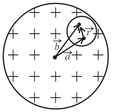
(a) , where volume charge density and position vector of the centre of the cavity relative to the centre of the sphere.
(b) Field inside the cavity is uniform and its direction is parallel to radial vector .
(c)
(iii) Electric field outside the cavity but inside the sphere:
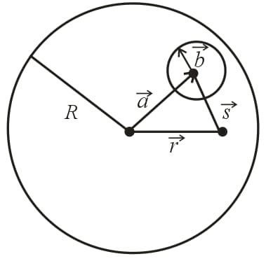
distance between centres of the cavity and the actual sphere,
radius of the cavity,
radius of sphere and radial distance of a point inside the sphere.
(iv) Electric field outside the sphere:
17. Electric Field Due to Cylinder With Cavity and Inside the Cavity:
Consider a non-conducting cylinder with volume charge density has a cylindrical cavity whose axis is at a radial distance from the axis of the actual cylinder. The electric field inside the cavity is,
18. Electrostatic Pressure on a Charged Conductor:
(i) , where surface charge density and electric field on the surface.
(ii) Force on part of the conductor is , where surface area of the part of the conductor.
(iii) Electrostatic stress, (or) , which can make the charge fly apart but held by the mechanical force of the conductor.
19. Electrostatic force of interaction between two halves of a spherical conductor of radius carrying a charge is .
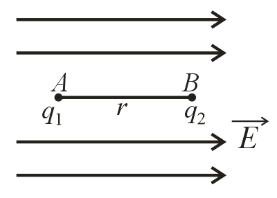
20. Motion of a Charged Particle in a Uniform Electric Field:
(i) When a charged particle is released in a uniform electric field from rest:
Consider a particle of charge and mass is released from rest in an electric field of strength . The particle will experience an electric force that causes its motion.
(a) The force experienced by the charged particle is .
(b) Acceleration produced by this force is .
(c) Consider a charged particle is released at point at time , and it reaches the point after time where its velocity becomes .
Take difference between and , separation between and as .
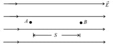
(d) Kinetic energy gained by the particle in time is,
or
(ii) According to work-energy theorem, we can say that gain in kinetic energy work done in the displacement of charge, i.e., , where potential difference between the two positions of charge .
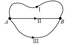
(iii) Work done in displacing a charge in an electrostatic field is path independent.
Work done from to is same along all the paths , and shown in the below figure.
(iv) When a charged particle enters with an initial velocity at a right angle to the uniform field:
When a charged particle enters perpendicularly in an electric field, it describes a parabolic path as shown.
(a) Equation of trajectory: Throughout the motion, the particle has uniform velocity along the -axis and horizontal displacement () is given by the equation .
(b) The motion of the particle is accelerated along -axis.
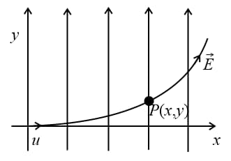
So, ; this is the equation of parabola which shows .
(c) Velocity at any instant:
At any instant t, and
So,
(d) If is the angle made by with -axis at time , then
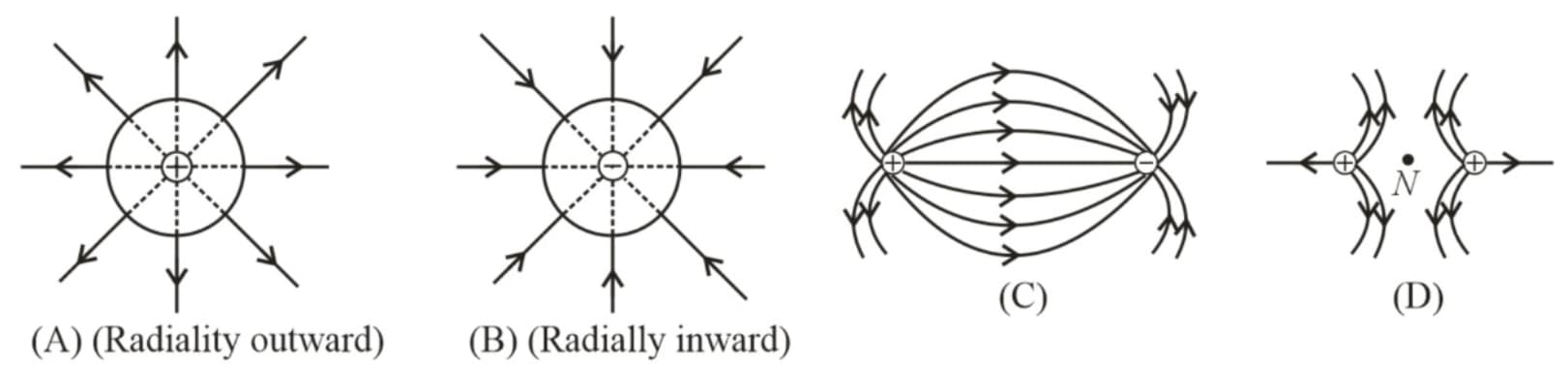
21. Electric Field Lines:
(i) Definition: An imaginary line in the field whose tangent represents the direction of the field at a point is called an electric field line.
(ii) Properties of electric field lines:
(a) Electric field lines originate at positive charge and terminate at negative charge.
(b) Tangent to the field line at any point gives the direction of the field at that point.
(c) Field lines never intersect each other. If they do, then the field should have two directions at that point that is impossible.
(d) Field lines are always normal to conducting surface.
(e) Field lines do not exist inside a conductor.
(f) The electrostatic field lines are open loops (while magneto static field lines form closed loops).
Note: Induced electric field lines are closed loops.
(g) The number of lines originating or terminating on a charge is proportional to the magnitude of charge, i.e., number of lines. In the following figure .
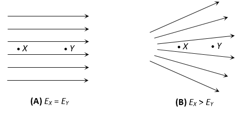
(h) If the lines of forces are equidistant and parallel straight lines of the field are uniform, and if either the line of force is not an equidistant or straight line or both, then the field will be non-uniform; also, the density of the field lines is proportional to the strength of the electric field.
22. Electric Flux :
(i) Electric flux leaving the surface is given by , if the field is uniform at every point on the surface. Here, is the angle between the electric field and the area vector .
(ii) , if the field is non-uniform.
(iii) Leaving flux is and entering flux is
(iv) Net flux passing through a surface is always zero.
23. Gauss’s Law:
The net electric flux leaving a closed surface is always equal to times the net charge enclosed.
(i) Electric flux through a circular disc :
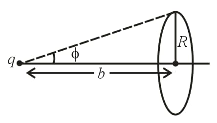
A point charge is placed at a distance from the centre of the circular disc of radius is,
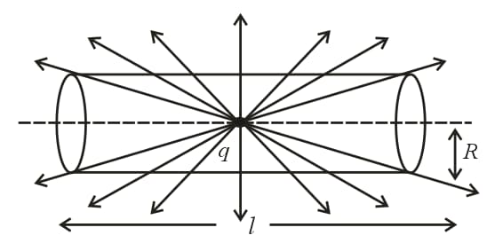
(ii) Electric flux through the lateral surface of a cylinder due to a point charge at its centre:
Consider a point charge is placed at the centre of the cylinder of length and radius . The flux through the curved surface is
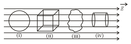
(iii) Net electric flux leaving a closed surface inside a uniform electric field is zero.
(iv) Electric flux through a cube when the charge is placed at its centre:
(a) Net flux through the cube:
(b) Flux through each face:
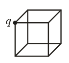
(v) If the charge is placed at the corner of a cube:
(a) Net flux through the cube:
(b) Flux through each face in contact with the charge is zero.
(c) Flux through each face which is not touching the charge is .
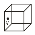
(vi) When the charge is placed at the centre of one of the faces, then flux through the cube is .
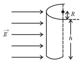
(vii) Electric flux leaving half-cylindrical surface in a uniform electric field:
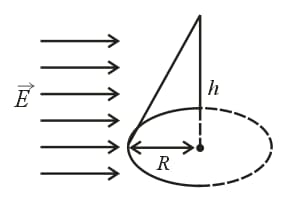
(viii) Electric flux leaving the conical surface in a uniform electric field:
(ix) Electric flux through a hemisphere in a uniform electric field:
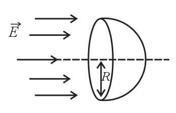
(a) Flux entering the flat face:
(b) Flux leaving the curved face:
(c) Net flux leaving the hemisphere:
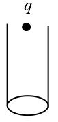
(x) Electric flux through an open cylinder:
(a) When a point charge is placed at the centre of the open side of the cylinder, the flux passing through the cylinder is .
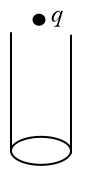
(b) When a point charge is placed just above the open side of the cylinder, the flux passing through the cylinder is .
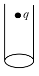
(c) When a point charge is placed just inside the open side of the cylinder, the flux passing through the cylinder is .
24. Electric Potential:
The amount of work done to move a unit positive charge from infinity to a certain point against the electric field.
(i)
(ii) Electric potential is a scalar.
(iii) S.I. unit: .
(iv) Dimension: .
(v) Positive charge gives positive potential and negative charge produces a negative potential.
25. Electric Potential Due to a Point Charge:
Electric potential due to a point charge at a distance is .
26. Electric Potential Difference:
The amount of work done to move a unit positive charge from one point to another against the electric field.
27. Consider two points and at distances and from a point charge , then
(i)
(ii) Potential decreases, if we move away from positive charge, i.e., is , if is .
(iii) Potential increases, if we move away from a negative charge, i.e., is , if is .
(iv) Work done to move a charge from to is,
(v)
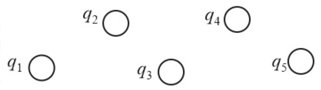
28. Electric Potential Due to a System of Charges:
The potential at a point is equal to the scalar sum of potential due to individual charges.
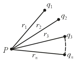
Potential at is
29. Potential Due to Infinite Charges on -Axis:
(i) When identical like charges are placed as shown, then the potential at origin is
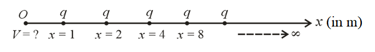
(ii) If the alternative charges are opposite, then
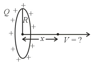
30. Potential Due to a Uniformly Charged Ring:
(i) At the centre of the ring, , where is charge on the ring, is radius and is linear charge density.
(ii) Potential at a point on the axis:
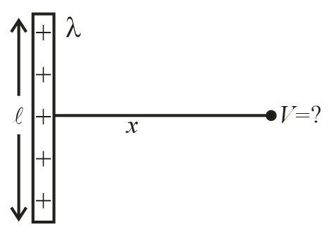
31. Electric Potential Due to a Charged Rod:
(i) On axis:
(ii) On perpendicular bisector:
32. Electric Potential Due to a Uniformly Charged Disc on Its Axis:
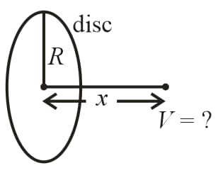
(i)
(ii) If then considering potential at as zero.
33. Potential Due to Infinite Line Charge:
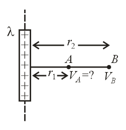
(i) (not defined) potential at a point due to infinite line charge cannot be determined, but potential difference can be calculated.
(ii)
34. Electric Potential on the Edge of a Uniformly Charged Disc:
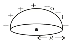
35. Electric Potential at Centre of a Uniformly Charged Hemispherical Shell:
36. Electric Potential Due to a Uniformly Charged Non-conducting Sphere:
(i) Potential outside the sphere,
or
(ii) Potential on the surface of sphere,
or
(iii) Potential inside the sphere is , where radius distance and volume charge density.
(iv) Potential at the centre is .
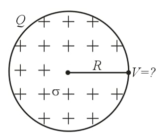
37. Potential Due to a Uniformly Charged Spherical Shell (or) Conducting Sphere:
(i) Potential inside the shell is equal to potential on the surface,
(ii) Potential outside the shell,
38. Potential Difference Between Two Concentric Shells:
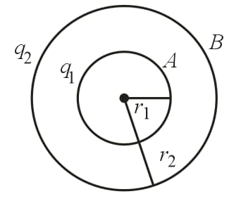
Consider two shells of radial and are concentric and have charges and . Then,
(i) Potential of shell is .
(ii) Potential of shell is .
(iii)
(a) If is , then .
(b) If is , then .
(c) Potential difference between the shells is independent of charge of the outer shell.
(d) If the two shells are connected by a conducting inner to outer shell. This is the principle of Van de Graff generator.
39. Potential Due to Three Concentric Shells:
The figure shows three conducting concentric shell of radii and having charges and , respectively.
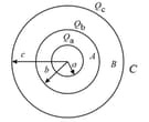
(i) Potential at is .
(ii) Potential at is .
(iii) Potential at is .
40. Earthing of Shell:
The figure shows two concentric spheres having radii and , respectively, . Charge on the inner sphere is .
(i) When the outer sphere is earthed:
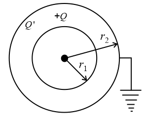
(a) Let be the charge on the outer surface, then
The potential at the surface of outer sphere,
(b) Potential of the inner sphere is .
(ii) In the above case, if the outer sphere is given a charge and the inner sphere is earthed, then
(a) In this case, the potential at the surface of the inner sphere is zero. So, if is the charge induced on the inner sphere,
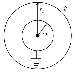
then i.e.,
(Charge on the inner sphere is less than that of the outer sphere)
(b) Potential at the surface of outer sphere:
41. Relation Between Electric Field and Potential Difference:
(i) If is the potential difference between two points separated by a distance in a uniform electric field on a straight line parallel to the field, then
.
(ii) In the above relation, negative sign indicates that the potential decreases if we move in the direction of the electric field.
(iii) Negative of the slope of the graph denotes the intensity of electric field, i.e., .
(iv) If the potential is a function of the coordinates , then the electric field in space can be written as , where and .
(v) If is the potential difference between two points separated by in a uniform electric field on a straight line making some angle to the field, then the electric field can be determined by knowing the boundary conditions,
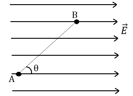
(vi) If an electric field is given in space, then the potential difference between two points in the space can be calculated as,
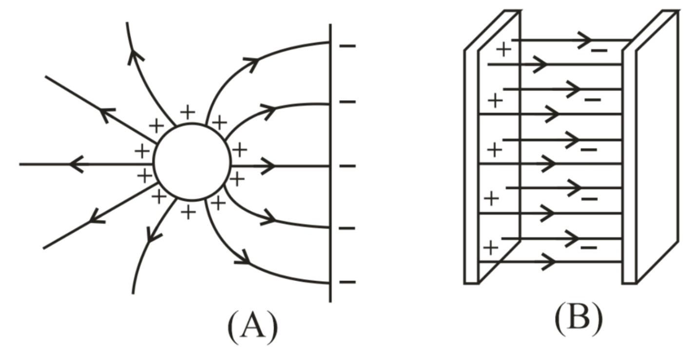
42. Equipotential Surface:
The locus of all points that are at the same potential is called the equipotential surface.
Regarding equipotential surface, the following points should be kept in mind:
(i) The direction of the electric field is perpendicular to the equipotential surfaces or lines.
(ii) The equipotential surfaces produced by a point charge or a spherically charge distribution are a family of concentric spheres.
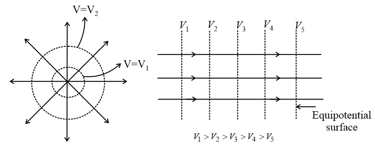
(iii) For a uniform electric field, the equipotential surfaces are planes perpendicular to the field lines.
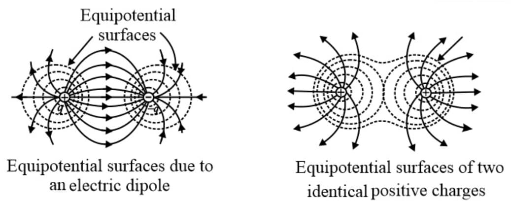
(iv) Equipotential surfaces due to electric dipole and two identical charges separated are shown in the below figure.
(v) A metallic surface of any shape is an equipotential surface.
(vi) Equipotential surfaces can never cross each other.
(vii) The work done in moving a charge along an equipotential surface is always zero.
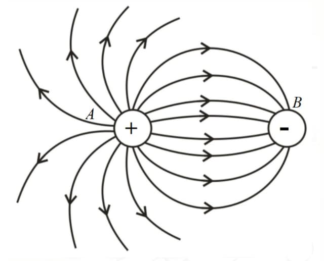
43. Electric Dipole:
Two equal and opposite charges separated by a small distance.
(i) Electric dipole moment :
The product of charge and length of the dipole.
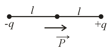
(a) Dipole moment,
(b) S.I. unit:
(c) Dimensions:
(d) It is a vector quantity.
(e) Its direction is always from to .
(ii) Electric field on axial line:
(a)
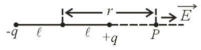
(b) For a short dipole:
(iii) Electric field on equatorial line:
(a)
(b) For short dipole, .
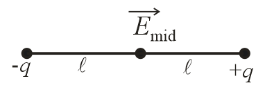
(iv) Electric field at the centre of dipole:
(v) Electric field at any general point due to a short dipole:
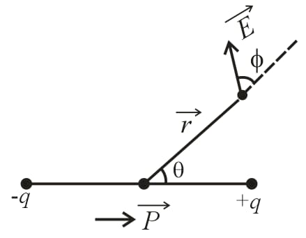
(a)
(b) If is the angle made by the electric field with position vector , then .
(vi) Electric potential at midpoint of the dipole, .
(vii) Potential on axial line, .
For
(viii) Potential at any point on an equatorial plane is zero.
(ix) Potential at any general point due to dipole is,
44. Dipole in a Uniform Electric Field:
(i) Net force on the dipole is zero.
(ii) Torque on dipole is .
, where is the angle between electric field and dipole moment.
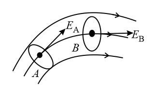
45. Dipole in a Non-uniform Electric Field:
(i) Force on the dipole,
(ii) Torque on the dipole is , where and are electric fields at the point charges.
46. Electrostatic Potential Energy:
(i) Potential energy of the two-particle system in an external electric field:
(ii) Potential energy of the two-particle system in an external electric field:
(iii) Potential energy of three particle system,
(iv) If the system has particles, then the number of terms in potential energy of the system is .
(v) Potential energy of short dipole in a uniform electric field is,
(a) If (minimum). The dipole is in stable equilibrium.
(b) If , (maximum). The dipole is in unstable equilibrium.
(c) If , then (reference point)
47. Equilibrium of Charged Soap Bubble:
(i) For a charged soap, bubble of radius and surface tension and charge density The pressure due to surface tension and atmospheric pressure act radially inwards and the electrical pressure acts radially outward.
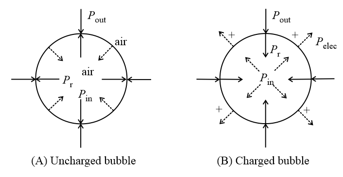
(a) The total pressure inside the soap bubble:
(b) Excess pressure inside the charged soap bubble:
(ii) If air pressure inside and outside is assumed equal, then
, i.e., . So,
(a) Charge density: Since ⇒
(b) Radius of bubble:
(c) Surface tension:
(d) Total charge on the bubble:
(e) Electric field intensity at the surface of the bubble:
(f) Electric potential at the surface:
48. Self-Energy:
(i) Self-energy of a hollow sphere,
(ii) Self-energy of a hollow sphere,
49. Interaction energy of a system is the sum of self-energies of the bodies and electrostatic interaction potential energies between the bodies.
50. Charge Distribution on Parallel Metal Plates:
(i) Charge on the outermost surfaces is equal to half the sum of the charges on all the plates.
(ii) Charges on the opposite plates are equal and opposite.
(iii) Example:
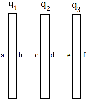
In this figure,
(a) Charges on the outer surfaces and are the same and equal to .
(b) Charges and .
(c) With number of plates, the maximum of capacitors can be formed.
51. Capacitor and Capacitance:
(i) A capacitor consists of two conductors carrying charges of equal magnitude and opposite sign.
(ii) The capacitance of any capacitor is the ratio of the charge on either conductor to the potential difference between them .
(iii) The capacitance depends only on the geometry of the conductors and not on an external source of charge or potential difference.
52. Dielectric:
Dielectrics are insulating (non-conducting) materials that transmit electric effects without conducting.
53. Polar Dielectrics:
A polar molecule has a permanent electric dipole moment even in the absence of an electric field; but, a polar dielectric has a net dipole moment zero in the absence of an electric field, because polar molecules are randomly oriented as shown in the figure.
54. Nonpolar Dielectric:
(i) In non-polar molecules, each molecule has a zero dipole moment in its normal state.
(ii) When an electric field is applied, molecules become induced electric dipole, e.g., , benzene, methane, etc., are made of non-polar atoms/molecules.
55. Dielectric Breakdown and Dielectric Strength:
(i) If a very high electric field is created in a dielectric, the dielectric then behaves like a conductor. This phenomenon is known as dielectric breakdown.
(ii) The maximum value of electric field (or potential gradient) that a dielectric material can tolerate without its electric breakdown is called its dielectric strength.
(iii) S.I. unit of dielectric strength of a material is but the practical unit is .
56. Parallel Plate Capacitor:
(i) , where charge on positive plate of the capacitor, capacitance of capacitor and potential difference between positive and negative plates.
(ii) Capacitance, , where is the surface area of plate and is the distance between the plates.
(iii) When complete space between the plates is occupied by a medium of dielectric constant , then .
(iv) Electric field between the plates:
(v) Energy density between the plates of the capacitor,
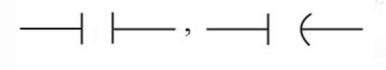
(vi) Representation of capacitor:
(vii) Attractive force between the capacitor plates:
57. Capacitor with Dielectric:
(i) Capacitance in the presence of dielectric:
(a) Capacitance when the gap between the plates of the capacitor is filled with a dielectric medium, then .
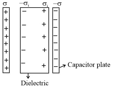
capacitance in the absence of dielectric.
(b) electric field in the absence of dielectric.
(c) , where surface charge density on capacitor plate and induced surface charge density on the surface of the dielectric.
(d) Field inside the slab is .
(e)
(f) Induced (bound) charge density:
58. Capacitance with Different Dielectrics:
(i) If a dielectric slab of thickness (less than the distance between the plates ) with dielectric constant is introduced between the plates of capacitor, then the new capacitance is
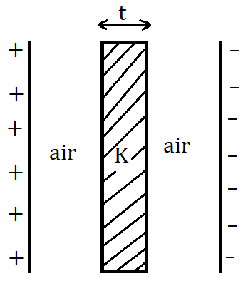
, where is the surface area of the plate.
Note: for metal plate inside the capacitor, . So,
(ii) Capacitor with multiple dielectrics:
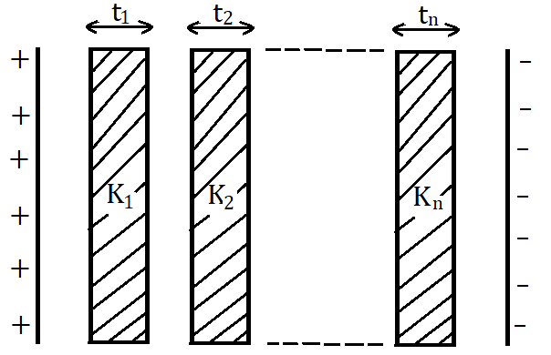
, where are thicknesses of dielectric slabs, are the dielectric constants of the slabs.
(iii) Capacitor with three different dielectrics:
(a) Case :
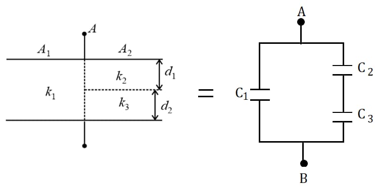
, and
The effective capacitance of the combination is .
(b) Case :
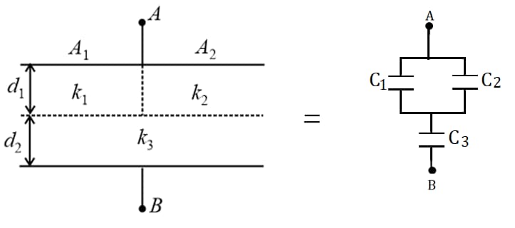
, and
The effective capacitance is .
59. Capacitance of an Isolated Spherical Conductor:
(i) in a medium, where is the radius of the sphere.
(ii) in air.
60. Spherical Capacitor:
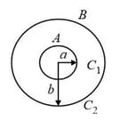
It consists of two concentric spherical shells as shown in the figure. Here, the capacitance of the region between the two shells is and that outside the shell is . We have,
and
(i) Case : If the outer shell is earthed, then the capacitance
(ii) Case : If the inner shell is earthed, then and will be in parallel.
So, the effective capacitance becomes .
(iii) Case : If there exists a potential difference between the inner shell and infinity, then and will be in series.
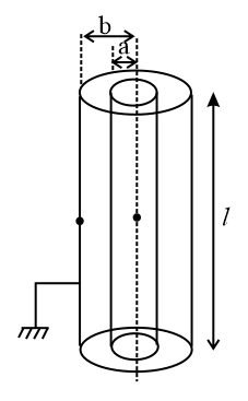
61. Cylindrical Capacitor:
It consists of two concentric cylinders of radii and , the inner cylinder is given charge while the outer cylinder is earthed. The common length of the cylinders is . then
62. Energy Stored in the Capacitor:
Consider a capacitor of capacitance is fully charged with a battery of emf . Then.
(i) the energy stored in the capacitor is /
(ii) Energy density , where relative permittivity of the medium, dielectric constant.
(iii) For vacuum, energy density .
(iv) In charging a capacitor by the battery, half the energy supplied is stored in the capacitor and the remaining half energy is lost in the form of heat.
63. Effect of Dielectric on the Energy Stored in a Capacitor:
(i) Case : Keeping the battery connection if a dielectric is inserted between the plates of a capacitor such that the gap is completely occupied, then the energy becomes .
(ii) Case : Keeping the charge constant if a dielectric is inserted between the plates of a capacitor such that the gap is completely occupied, then the energy becomes .
64. Heat Produced in the Capacitive Circuit:
Heat Work done by battery change in potential energy of capacitors.
(i) Case :
Consider a capacitor of capacitance is connected across a battery of emf . Then,
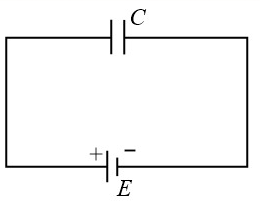
The heat lost on reversing the terminals of the battery is,
(ii) Case :
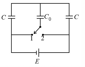
In the given figure, the heat lost when the switch is shifted from is,
65. Combination of Capacitors:
(i) Series combination:
Consider three capacitors of capacitances , and are connected in series as shown in the figure.
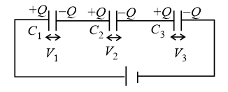
(a) Charge on all capacitors is the same.
(b) The effective capacitance can be calculated using the formula, .
(c) Ratio of the potential differences across capacitors, .
(ii) Parallel combination:
Consider three capacitors of capacitances , and are connected in parallel as shown in the figure.
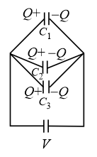
(a) Potential difference is the same across all capacitors.
(b) The effective capacitance of the combination is .
(c) The ratio of charges on the capacitors: .
66. Coalesce of Charged Drops:
Suppose, we have identical drops each having radius , capacitance , charge , potential and potential energy .
If these drops are combined to form a big drop of radius , capacitance , charge , potential and potential energy , then
(i) Charge on big drop: .
(ii) Radius of big drop: Volume of big drop volume of a single drop.
i.e., ,
(iii) Capacitance of big drop: .
(iv) Potential of big drop: .
(v) Energy of big drop: .
(vi) Energy difference: Total energy of a big drop is greater than the total energy of all smaller drops. Hence, energy difference .
67. Distribution of Charges on Connecting Two Charged Capacitors:
When two capacitors of capacitances and with potentials and are connected as shown in the figure.
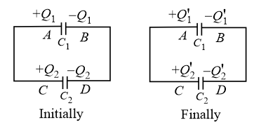
(i) Common potential:
(ii) Final charge on the first capacitor:
(iii) Final charge on the second capacitor:
(iv) Heat loss during the redistribution of charge:
The loss of energy is in the form of Joule heating in the wire.
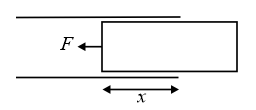
68. Force on Dielectric:
(i) When the battery is connected, the force on the dielectric is , where is the breadth of the dielectric, is the dielectric constant, is the distance between the plates and is the voltage applied across the capacitor.
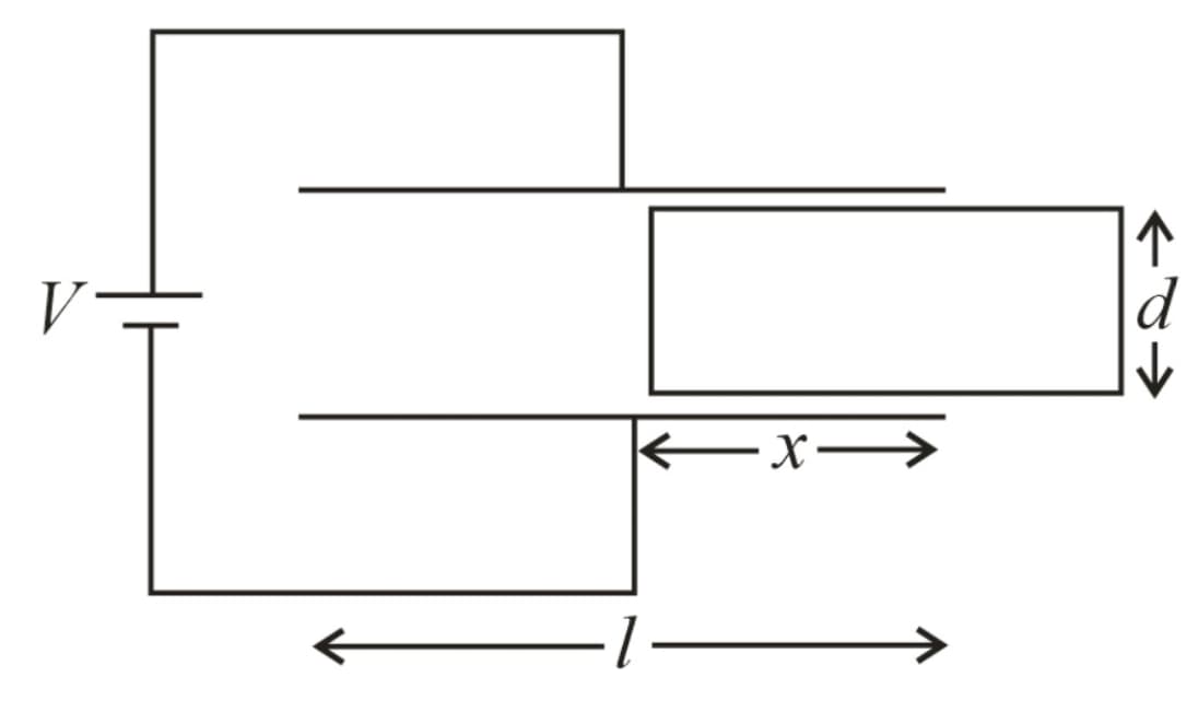
Note that, the force is constant and independent of the length of the part of the dielectric inside the capacitor .
(ii) When the battery is not connected,
i.e., , where is the width of the plate or dielectric slab.
(iii) Force on the dielectric will be zero when the dielectric is fully inside.
69. Circuit for Source:
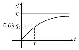
(i) Charging of capacitor:
(a) Charge on the capacitor (capacitor initially uncharged) at time is
, where charge on the capacitor at steady state.
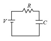
(b)
(c) Time constant, .
(d) Current at a given time is .
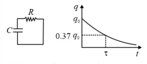
(ii) Discharging of capacitor:
(a) Charge on the capacitor at time is .
initial charge on the capacitor
(b) Current at time is .