
What are the advantages of using soft iron as a core, instead of steel, in the coils of galvanometers?
Important Points to Remember in Chapter -1 - Magnetic Properties of Matter from H C Verma CONCEPTS OF PHYSICS [VOLUME 2] Solutions
1. Magnetic Field Due to a Moving Point Charge in Vector Form:
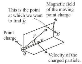
Consider a particle of charge is moving with velocity . The magnetic field due to this charge at position relative to the charge is
2. Biot–Savart's Law:
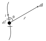
(i) Magnetic field due to the current element , at position is , where
absolute permeability of air or vacuum
(ii) Net magnetic field due to the entire wire,
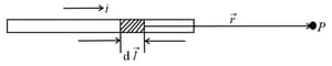
(iii) For the axial position of wire: When point lies on the axial position of current-carrying conductor, then the magnetic field at is . Since the angle between the current direction and position vector is .
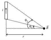
3. Magnetic Field Due to a Finite Straight Wire:
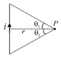
Magnetic field due to a finite wire carrying current whose ends are making angles and with the perpendicular of the wire passing through the point of observation at a distance is,
4. Magnetic field due to a finite wire at any general point as shown below is,
5. Magnetic Field Due to a Spiral:
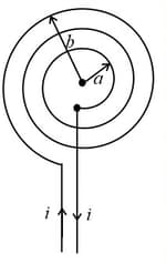
Magnetic field due to spiral-shaped coil carrying a current having inner and outer radii as and is,
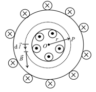
6. Magnetic Field Due to a Cylinder with Cavity:
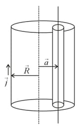
The field at the axis of the cavity is , where is the current density and is the distance between the axes of the actual cylinder and cavity.
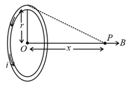
7. Magnetic Field Due to Circular Loop:
(i) Magnetic field due to a circular coil of radius with number of turns carrying current at the centre of a circular coil: .
(ii) If a coil of radius carrying current , then the magnetic field on its axis at a distance from its centre given by .
(iii) For , field on the axis is , where Area of each turn of the coil.
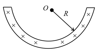
8. Magnetic Field at the Centre of a Circular Arc:
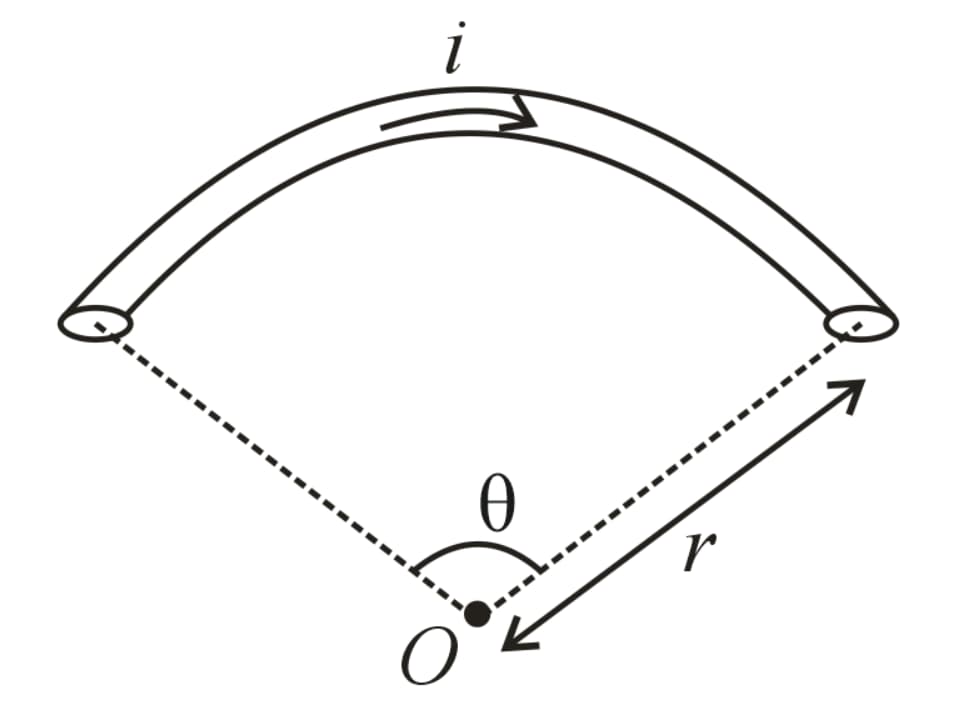
Magnetic field due to a circular arc of radius carrying current subtending angle at its centre is
, where is in .
9. Magnetic Field at the Centre of an Equilateral Triangle:
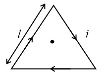
Consider an equilateral triangular coil of side length carrying current . The magnetic field at its centre is,
10. Magnetic Field at the Centre of a Square:
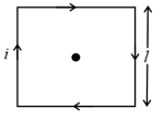
Consider a square coil of side length carrying current . The magnetic field at its centre is,
11. Magnetic Field at the Centre in the Following Situation:
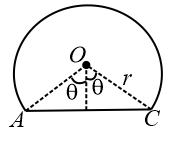
A straight wire is joined with the circular arc of radius as shown in the figure. It is carrying current and the straight wire is subtending an angle . The magnetic field at its centre is,
12. Magnetic Field Due to Polygon of Sides:
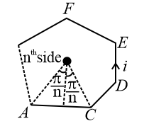
Consider a polygon of sides of side a carrying current . The magnetic field at its centre is,
13. Field Due to Half Long Cylindrical Wire:
Current flows along the length of a long straight semi cylindrical-shaped wire with a cross-section having the form of a thin half-ring of radius . The field along the axis is,
14. Solenoid:
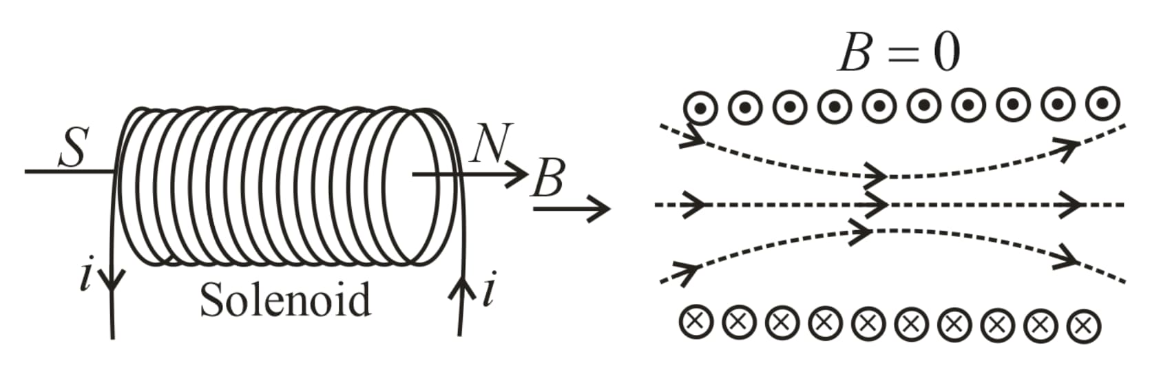
A magnetic field is produced around and within the solenoid. The magnetic field within the solenoid is uniform and parallel to the axis of the solenoid.
(i) Magnetic field on the axis of the finite solenoid:
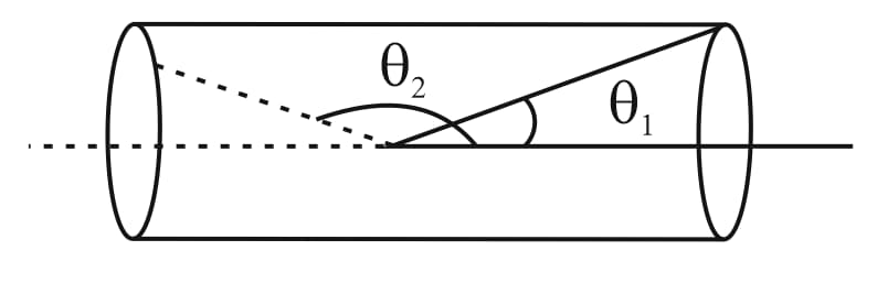
Consider a finite solenoid with turns per unit length carrying current . Let and be the angles made by the ends of the solenoid with its axis as shown in the figure.
(ii) Magnetic field inside the long solenoid is . It is uniform and parallel to the axis.
(iii) Magnetic field due to semi solenoid (at one end of the solenoid) is .
15. Toroid:
A toroid can be considered as a ring shaped closed solenoid. Hence, it is like an endless cylindrical solenoid.
Consider a toroid having turns per unit length and radius . The magnetic field at a point in the figure is given as
, where and is the total number of turns in the coil.
16. Ampere’s Law:
The line integral of over a closed loop is times the net current enclosed.
17. Magnetic Field due to Infinite Straight Wire:
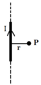
Consider an infinite straight long wire carrying current . The magnetic field at a perpendicular distance is,
18. Magnetic Field due to a Long Cylindrical Thin Shell:
Consider a cylindrical thin shell of radius carrying current . Then
(i) Magnetic field inside the shell, .
(ii) Magnetic field outside the shell, .
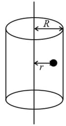
19. Magnetic field due to a cylinder:
(i) Field outside the cylinder:
Consider a long solid cylinder of radius , carrying current .
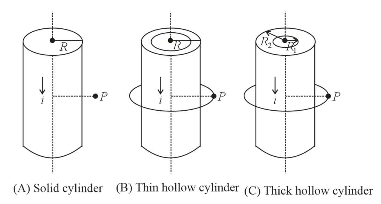
Magnetic field outside the wire at in all the cases , where is the radial distance from the centre.
(ii) Magnetic field inside the hollow region of cylinder:
(iii) Inside the solid cylinder:
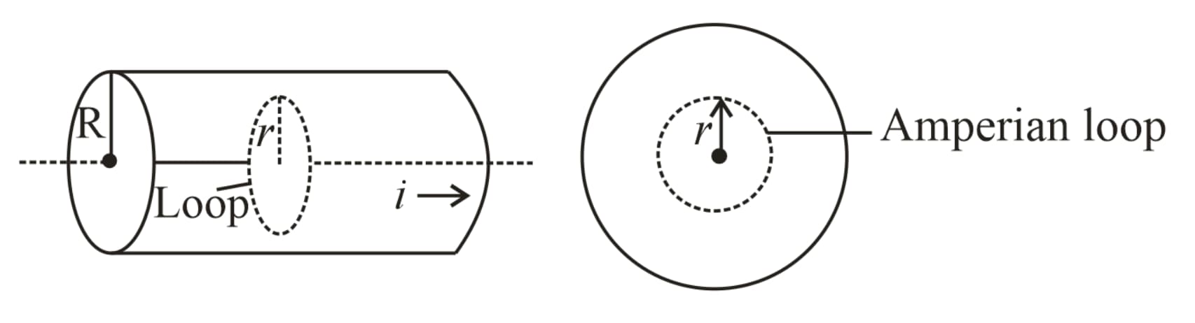
The field at a point inside is , for
(iv) Inside the thick portion of hollow cylinder:
(a) Current enclosed by the loop is given as , where and are internal and external radii, respectively.
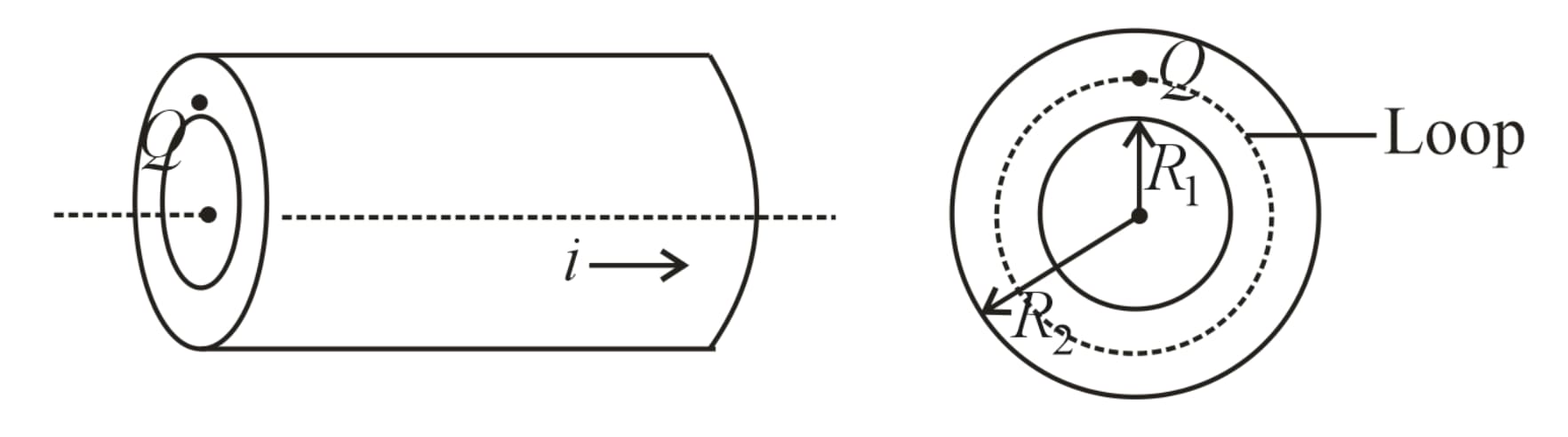
(b) Magnetic field at point is .
20. Magnetic Field due to an Infinitely Thin Sheet (Ribbon) Carrying Current:
The figure shows an infinite sheet of current with linear current density, . Due to symmetry, the field line pattern above and below the sheet is uniform. Consider a square loop of side as shown in the figure.
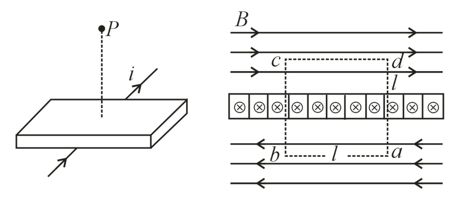
(by Ampere’s law)
The current enclosed by the loop is .
The magnetic field at point is .
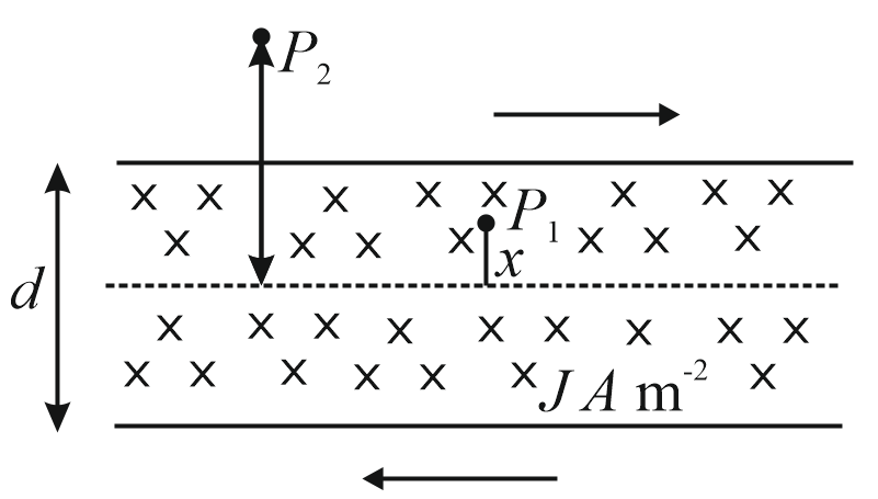
21. Magnetic Induction due to a Thick Sheet:
Consider a thick sheet of thickness with current density .
(i) At point .
(ii) At point , where is the distance from the axis.
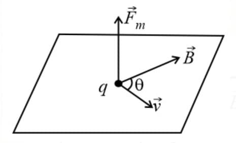
22. Magnetic Force Acting on a Moving Point Charge:
If a particle of charge moving with a velocity in a magnetic field , then the magnetic force on the particle is
(i) Direction of force:
The force is always perpendicular to both the velocity and the field in accordance with right-hand screw rule, though and themselves may or may not be perpendicular to each other.
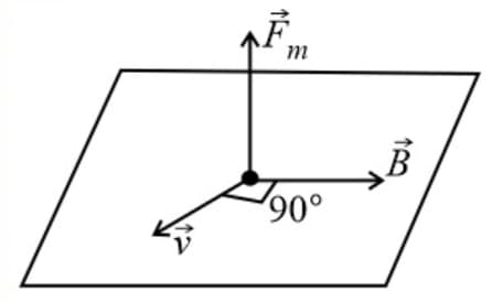
(ii) Fleming's left-hand rule:
Stretch the forefinger, middle finger and thumb of the left hand such that they are mutually perpendicular. If the forefinger indicates magnetic field, the middle finger indicates the direction of motion of the positive charge, then the thumb indicates the direction of the force.
23. Motion of a Charged Particle in a Magnetic Field:
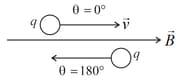
(i) Straight line motion:
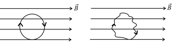
If the direction of is parallel or antiparallel to , then or and therefore, . Hence, the trajectory of the particle is a straight line (travels undeviated).
(ii) Circular motion of a charged particle in a uniform magnetic field:
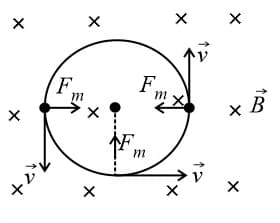
(a) Motion of charged particle is always perpendicular, i.e., .
(b) In this case, path of a charged particle is circular and magnetic force provides the necessary centripetal force, i.e., .
(c) Radius of path, , where momentum of charged particle, and kinetic energy of the charged particle (gained by charged particle after accelerating through potential difference ), then
(d) Time period of the particle, . The time period or frequency is independent of the speed of the particle.
(e) Kinetic energy, is always constant.
(f) Work done by the magnetic force is zero.
(iii) Helical motion of a charged particle in a uniform magnetic field:
Consider a particle of mass having charge enters a magnetic field of induction at an angle (other than ), then the particle moves in a helical path.
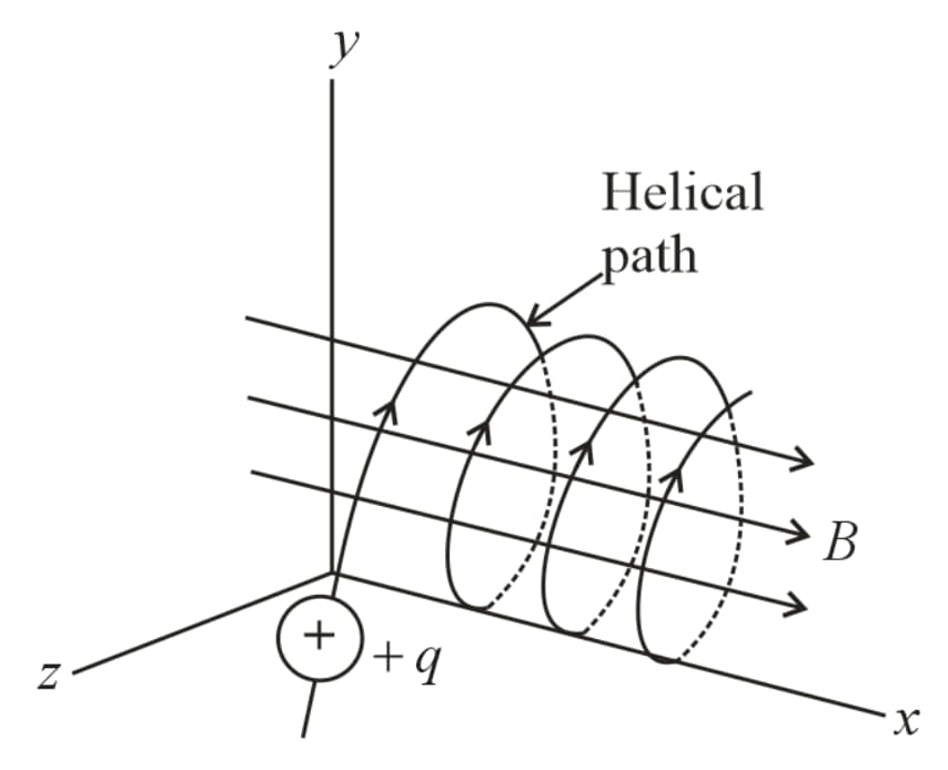
(a) Force on the particle,
(b) The radius of the helix is
(c) Time period does not depends on velocity and they are given by
and frequency
(d) The pitch of the helix, (i.e., distance traveled parallel to the field in one revolution) will be given by,
(e) If pitch value is , then the number of pitches obtained in length given as,
Number of pitches , and time required
(iv) Lorentz's force:
If a particle of charge moving with velocity in a combined electric field and magnetic field , then the net force on the charged particle is,
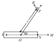
24. Circular Motion of Charged Particle When the Width of the Field is Less than the Radius of the Circular Path:
Consider particle of charge enter a uniform magnetic field of induction with speed and width perpendicular to it.
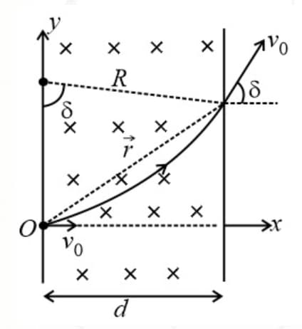
(i) Angle of deviation :
(a) If , then
(b) If , then
(c) Deviation angle in terms of the time of travel,
(ii) Position vector of a particle at a given time:
(iii) Velocity vector at a given time:
25. Motion of Charge in a Combined Electric Field and Magnetic Field:
(i) When motion will be uniformly accelerated in a straight line as
(ii)
(iii) So, the particle will be either speeding up or speeding down.
(iv) When and motion will be uniformly accelerated in a parabolic path.
(v) When the particle may move undeflected with the same uniform speed if (this is called as velocity selector condition)
26. Magnetic Force on a Current Carrying Wire:
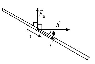
(i) Magnetic force on a straight current carrying wire in a uniform magnetic field is,
current in the straight conductor,
length of the conductor in the direction of the current in it,
magnetic induction (uniform throughout the length of the conductor)
(ii) In general, force is
(iii) In the figure given below, the force on the curved wire is,
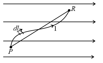
The force experienced by a wire of any shape is equivalent to force on a wire joining points in a uniform magnetic field.
(iv) Magnetic force on a closed loop in a uniform is zero.
Here, over a closed loop is zero.
(v) If the magnetic field is perpendicular to the plane of the current loop as shown below figure, then
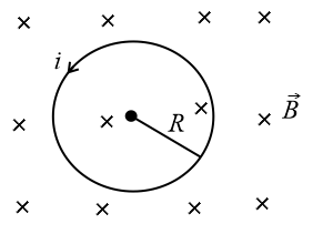
Magnetic force on the loop is radially inwards, so tension develops in the ring.
(a) Tension,
(b) If is the cross-section of the wire of the ring, then stress is
(c) It is the breaking stress, then the maximum magnetic field required to rupture the winding is
(vi) If a hypothetical magnetic field is along the radial lines from the center of the ring, then
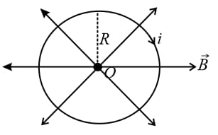
The magnetic force on the ring is
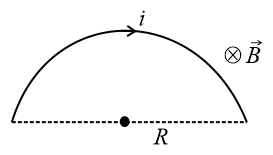
(vii) Magnetic force on the semicircular ring,
27. Magnetic Interaction Force Between Two Parallel Long Straight Currents:
When two long straight linear conductors are parallel and carry a current in each, they magnetically interact with each other, one experiences a force. This force is of:
(i) Repulsion, if the currents are anti-parallel (i.e., in opposite direction).
(ii) Attraction, if the currents are parallel (i.e., in the same direction).
(iii) This force per unit length on either conductor is given by , where , are currents in the parallel wires, perpendicular distance between the parallel conductors.
28. Magnetic Torque on a Closed Current Circuit:
(i) When a plane closed current circuit of turns and of area per turn carrying a current is placed in a uniform magnetic field, it experiences a zero-net force, but experience a torque given by
(ii) , where area vector outward from the face of the circuit where the current is anticlockwise, magnetic induction of the uniform magnetic field.
magnetic moment of the current circuit
Note: This expression can be used only if is uniform otherwise calculus will be used.
29. Potential Energy of a Dipole in a Magnetic Field:
, where is the angle between magnetic moment and field.
30. Moving Coil Galvanometer:
(i) It consists of a plane coil of many turns suspended in a radial magnetic field. When a current is passed in the coil it experiences a torque that produces a twist in the suspension. This deflection is directly proportional to the torque
(ii) , where elastic torsional constant of the suspension.
(iii) , where galvanometer constant.
(iv) Force experienced by a magnetic dipole in a non-uniform magnetic field: , where magnetic dipole moment.
31. Cyclotron:
(i) Cyclotron is a device used to accelerated positively charged particles (like, -particles, deuterons, etc.) to acquire enough energy to carry out nuclear disintegration, etc.
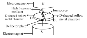
(ii) It is based on the fact that the electric field accelerates a charged particle and the magnetic field keeps it revolving in circular orbits of constant frequency.
(iii) It consists of two hollow -shaped metallic chambers, and , known as dees. The two dees are placed horizontally with a small gap separating them. The dees are connected to the source of high-frequency electric field. The dees are enclosed in a metal box containing a gas at a low pressure of the order of mercury. The whole apparatus is placed between the two poles of a strong electromagnet as shown in the figure. The magnetic field acts as perpendicular to the plane of the dees.
(iv) Time taken by ion to describe a semicircular path is given by
(v) If time period of the oscillating electric field, then
(vi) The cyclotron frequency,
(vii) Maximum energy gained by the charged particle , where maximum radius of the circular path followed by the positive ion.
32. Gilbert’s Magnetism (Earth’s Magnetic Field):
(i) The line of earth's magnetic induction lies in a vertical plane coinciding with the magnetic north-south direction at that place. This plane is called magnetic meridian.
(ii) Earth's magnetic axis is slightly inclined to the geometric axis of the earth and this angle varies from to .
(iii) The earth's magnetic poles are opposite to the geometric poles, i.e., at earth's north pole, its magnetic south pole is situated and vice versa.
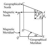
33. Elements of Earth's Magnetic Field:
The magnitude and direction of the magnetic field of the earth at a place are completely given by certain quantities are known as magnetic elements.
(i) Magnetic declination :
It is the angle between geographic and magnetic meridian planes.
Declination at a place is expressed at or depending upon whether the north pole of the compass needle lies to the east or to the west of the geographical axis.
(ii) Angle of inclination or dip :
It is the angle between the direction of intensity of the total magnetic field of earth and a horizontal line in the magnetic meridian.
(iii) Horizontal component of earth's magnetic field
Earth's magnetic field is horizontal only at the magnetic equator. At any other place, the total intensity can be resolved into a horizontal component and vertical component .
Also, and
By squaring and adding equations and , we get,
Dividing equation by equation ,
34. Magnetic Moment of a Current Carrying Loop:
Consider a coil of area , having turns, is carrying current . Its magnetic moment is .
35. Torque Acting on a Current Loop:
Consider a current loop of magnetic moment is placed in a uniform magnetic field of induction , then the torque on the coil is .
36. Magnetic Field due to a Single Pole:
Magnetic field induction due to a magnetic pole of pole strength at a distance is
.
37. Magnetic Field on the Axis of the Magnet:
, where is the magnetic moment of the bar magnet and is the distance on the axial line of a magnet.
38. Magnetic Field on the Equatorial Axis of the Magnet:
, where is the magnetic moment of the bar magnet and is the distance on the equatorial line of the magnet.
39. Magnetic Field at Point due to Bar Magnet:
, where is the magnetic moment of the bar magnet and is the distance of any general point from the magnet and is the angle made by with moment .
40. Magnetic Moment of a Rotating Charge:
If a charge is rotating at an angular velocity then
(i) its equivalent current is given as ,
(ii) its magnetic moment is .
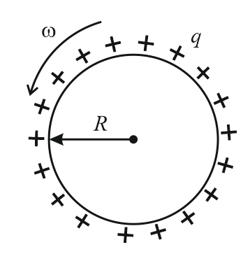
(iii) The ratio of magnetic moment to the angular momentum of a uniform rotating object which is charged uniformly is always a constant. Irrespective of the shape of the conductor .
41. Magnetic Dipole:
(i) Magnetic moment , where pole strength of the magnet and is magnetic length .
(ii) Magnetic field at axial point (end-on) of dipole , where is the magnetic moment of the bar magnet and is the distance.
(iii) Magnetic field at equatorial position (broad side-on) of dipole .
(iv) At a point which is at a distance from dipole midpoint and making angle with dipole axis:
(a) Magnetic potential,
(b) Magnetic field,
(v) Torque on dipole placed in a uniform magnetic field,
(vi) Potential energy of dipole placed in a uniform field,
42. Magnetic Materials:
On the basis of mutual interactions or behavior of various materials in an external magnetic field, the materials are divided in three main categories.
(i) Diamagnetic materials:
Diamagnetism is the intrinsic property of every material and it is generated due to mutual interaction between the applied magnetic field and orbital motion of electrons.
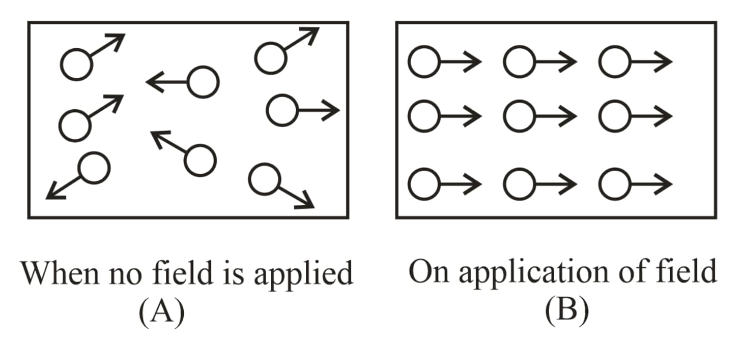
(ii) Paramagnetic materials:
In these substances, the inner orbits of atoms are incomplete. The electron spins are uncoupled, consequently, on applying a magnetic field, the magnetic moment generated due to the spin motion aligns in the direction of the magnetic field and induces magnetic moment in its direction due to which, the material gets feebly magnetized. In these materials, the electron number is odd.
(iii) Ferromagnetic materials:
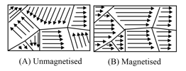
(a) In some materials, the permanent atomic magnetic moments have a strong tendency to align themselves even without any external field. These materials are called ferromagnetic materials.
(b) In every unmagnetized ferromagnetic material, the atoms form domains inside the material. Different domains, however, have different directions of magnetic moment and hence, the materials remain unmagnetised. On applying an external magnetic field, these domains rotate and align in the direction of the magnetic field.
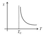
(iv) Curie’s law:
(a) The magnetic susceptibility of paramagnetic substances is inversely proportional to its absolute temperature, i.e., , where Curie constant, absolute temperature.
(b) On increasing the temperature, the magnetic susceptibility of paramagnetic materials decreases and vice versa.
(c) The magnetic susceptibility of ferromagnetic substances does not change according to Curie's law.
(v) Curie temperature :
(a) The temperature above which a ferromagnetic material behaves like a paramagnetic material is defined as Curie temperature .
(b) The minimum temperature at which a ferromagnetic substance is converted into a paramagnetic substance is defined as Curie temperature.
(c) For various ferromagnetic materials, its values are different, e.g., for for , for ,
(d) At this temperature, the ferromagnetism of the substances suddenly vanishes.
(vi) Curie–Weiss’s law:
At temperatures above Curie temperature, the magnetic susceptibility of ferromagnetic materials is inversely proportional to
i.e.,
, here Curie temperature.
43. Hysteresis Curve:
For ferromagnetic materials, by removing the external magnetic field, i.e., , the magnetic moment of some domains remains aligned in the applied direction of the previous magnetising field which results in a residual magnetism.
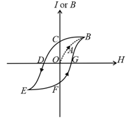
The lack of traceability as shown in the figure is called hysteresis and the curve is known as the hysteresis loop.
(i) Retentivity:
(a) When is reduced, reduces, but is not zero when .
(b) The remainder value of magnetisation when is called the residual magnetism or retentivity.
(c) The property by virtue of which the magnetism remains in the material even on the removal of magnetising field is called retentivity or residual magnetism.
(ii) Coercivity or coercive force:
(a) When magnetic field is reversed, the magnetisation decreases and for a particular value of denoted by , it becomes zero, i.e., when . This value of is called the coercivity.
(b) Magnetic hard substance (steel) High coercivity
(c) Magnetic soft substance (soft iron) Low coercivity
44. Some Important Formulas in Magnetisation:
(i) Intensity of magnetisation: .
(ii) Magnetic induction inside the magnetising material: .
(iii) Magnetic permeability: .
(iv) Magnetic susceptibility: .
(v) Curie’s law: .
(vi) Curie–Wiess’s law:
For ferromagnetic materials, , where Curie temperature.


