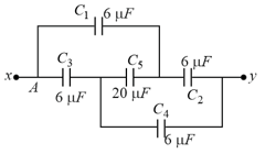
What is the effective capacitance between points X and Y?
Important Questions on Capacitance

When a thick slab is introduced between all the plates, in order to maintain the same potential difference, the distance between the plates is increased by . Find the dielectric constant of the slab.
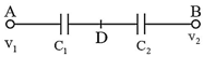
The equivalent capacitance between and in the circuit is given below.
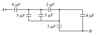
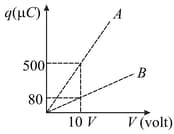
Figure shows charge versus voltage graph for series and parallel combination of two given capacitors. The capacitances are:
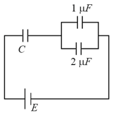
In the circuit shown, find if the effective capacitance of the whole circuit is to be All values in the circuit are in
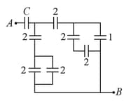
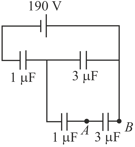
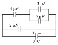
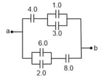
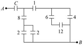
Figure shows a network of capacitors where the number indicates capacitances in micro Farad. The value of capacitance C if the equivalent capacitance between point A and B is to be is :
Three capacitances, each of 3 , are provided. These cannot be combined to provide the resultant capacitance of :
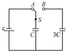
The figure shows a capacitor of capacitance connected to a battery via a switch, having a total charge on it, in steady-state. When the switch is turned from position to position , the energy dissipated in the circuit is