
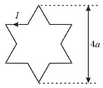
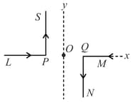
Which one of the following options represents the magnetic field at due to the current flowing in the given wire segments lying on the plane?
Important Questions on Magnetic Effect of Current
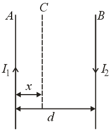
An arrangement of three parallel straight wires placed perpendicular to plane of paper carrying same current along the same direction is shown in Figure. Magnitude of force per unit length on the middle wire is given by
Consider two straight parallel conductors and separated by a distance and carrying individual currents respectively. If the two conductors attract each other, it indicates that
A rigid square loop of side and carrying current is lying on a horizontal surface near a long current carrying wire in the same plane as shown in figure. The net force on the loop due to the wire will be:
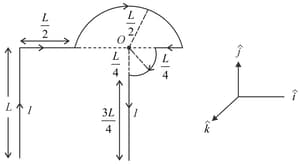
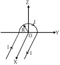
A wire carrying current has the shape as shown in adjoining figure. Linear parts of the wire are very long and parallel to -axis while semicircular portion of radius is lying in - plane. Magnetic field at point is :

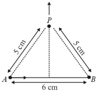
Find the magnetic field at point due to a straight line segment of length carrying a current of (See figure)
As shown in the figure, two infinitely long, identical wires are bent by and placed in such a way that the segments and are along the - axis, while segments and are parallel to the - axis. If and the magnitude of the magnetic field at is and the two wires carry equal currents (see figure), the magnitude of the current in each wire and the direction of the magnetic field at will be
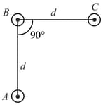
Two very long, straight, and insulated wires are kept at angle from each other in plane as shown in the figure.
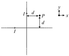
These wires carry currents of equal magnitude , whose direction are shown in the figure. The net magnetic field at point will be:
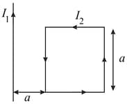
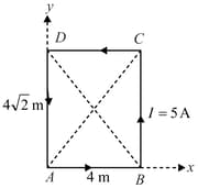
A rectangular conducting loop of length and breadth carrying a current of in the anti-clockwise direction is placed in the -plane. The magnitude of the magnetic induction field vector at the intersection of the diagonal is
Two long straight parallel wires, carrying (adjustable) currents and , are kept at a distance apart. If the force between the two wires is taken as 'positive' when the wires repel each other and 'negative' when the wires attract each other, the graph showing the dependence of , on the product , would be:
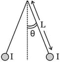
Two long currents carrying thin wires, both with current , are held by insulating threads of length L and are in equilibrium as shown in the figure, with threads making an angle ' ' with the vertical. If wires have a mass per unit length then the value of is:
( gravitational acceleration)


