
AC Voltage Applied to a Inductor
AC Voltage Applied to a Inductor: Overview
This topic covers concepts, such as Pure Inductance AC Circuit, Reactance, Inductive Reactance, Variation of Inductive Reactance with AC Frequency, Choke Coil, Phasor Diagram for Pure Inductance Circuit, Average Power in Pure Inductive Circuit, etc.
Important Questions on AC Voltage Applied to a Inductor
An inductor of inductance is connected to a a.c. source. Let inductive reactance in the circuit is . If a d.c. source replaces the a.c. source in the circuit, then the inductive reactance in the circuit is . and respectively are
An inductor of inductance is connected to a a.c. source. Let the inductive reactance in the circuit be . If a dc source replaces the ac source in the circuit, then the inductive reactance in the circuit is. , respectively are:
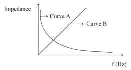
As per the given graph, choose the correct representation for curve and curve
{Where Reactance of pure capacitive circuit connected with A.C. source
Reactance of pure inductive circuit connected with A.C. source
Impedance of pure resistive circuit connected with A.C. source
Impedance of the series circuit }
The variation of impedance with angular frequency for two electrical elements is shown in the graph given.
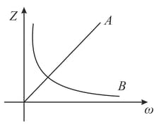
If and are inductive reactance, capacitive reactance and resistance respectively, then
A coil of inductance and resistance is connected to a source of and . The phase difference between the voltage maximum and the current maximum is
Statement 1: An ac circuit can be created with zero reactance.
Statement 2: An ac circuit without power is not possible.
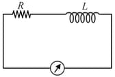
In the circuit shown, a d.c. source gives a current as recorded in the ammeter and a.c. source of frequency) gives a current . The inductive reactance is
In the circuit shown in the figure the inductance of coil is and capacitance of the capacitor is . The circuit is powered by an A.C. voltage source. If value of current measured by ammeter does not depend on resistor, then frequency of source is:
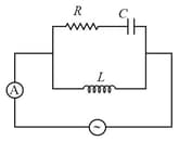
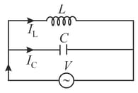
If the current in inductance is and that in capacitance is . What is the current drawn from the source?
The average power dissipated in a pure inductance is
The graph between inductive reactance and frequency is
Peak value fo a.c in purely inductive circuit is
When ac voltage applied to circuit containing inductor only lagging of current with voltage by
The average power dissipated in a pure inductor is
The reactance of an inductor at is The reactance of it at is:
A choke is preferred to a resistance for limiting current in ac circuit because:
A series circuit is connected to a voltage source with . After a very large time, current behaves as :
A resistance of and an inductance of henry are connected in series to an ac voltage of volts and frequency. The phase angle between the voltage and current is :-
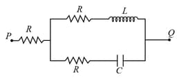
A voltage (where, is a real amplitude) is applied between the points and in the network shown in the figure. The values of capacitance and inductance are and . Then, the total impedance between and is
The current can be reduced in circuit without power loss by-


