
AC Voltage Applied to a Inductor
AC Voltage Applied to a Inductor: Overview
This topic explains the results when an AC voltage is applied to an inductor. Magnetisation and demagnetisation are also explained here in detail.
Important Questions on AC Voltage Applied to a Inductor
The average power dissipated in a pure inductance is
A pure inductor of Is connected to a source of . Find the inductive reactance and Current in the circuit if the frequency of the source is
What is phasor diagram draw phasor diagram for purely inductive circuit?
Maximum value of voltage is attained in time earlier than to . This statement is
The graph between inductive reactance and frequency is
Peak value fo a.c in purely inductive circuit is
When ac voltage applied to circuit containing inductor only lagging of current with voltage by
The average power dissipated in a pure inductor is
A inductor is connected to supply. What is the average power of the circuit over a complete cycle
In a pure inductive circuit negative and positive loop under power curve is the same.
The average power supplied to an inductor over one complete cycle is zero.
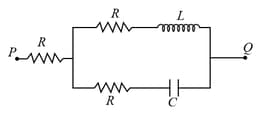
A voltage (where, is a real amplitude) is applied between the points and in the network shown in the figure. The values of capacitance and inductance are and . Then, the total impedance between and is
A coil has inductance of . Find its reactance at .
How the inductive and capacitive reactances are affected by increasing AC frequency?
The current in an inductive circuit is given by . Give the equation for voltage.
Explain the theory of AC circuit with inductor. Draw phasor diagram of voltage and current in each case.
Explain the term: Inductive reactance.
Find inductive reactance for inductor at frequency. Find current in the inductor if voltage applied is .
The current can be reduced in circuit without power loss by-
The current lags the voltage by in phase, when the circuit has-


